
7 Common Mistakes in Topographical Survey Reports for Piping
In my two decades of piping engineering, I have seen multi-million dollar projects derailed by a single faulty benchmark. A topographical survey report is the foundation of your entire plant layout; if the ground data is flawed, every subsequent stress analysis, pipe rack elevation, and equipment nozzle orientation becomes a liability.
Many engineers treat survey reports as “given” data, but I have learned the hard way that verification is non-negotiable. Whether it is a missing underground utility or a misaligned coordinate system, these errors inevitably lead to costly field rework and schedule delays. This guide breaks down the seven most frequent pitfalls I encounter in survey deliverables and how you can mitigate them before they hit the construction phase.
Key Takeaways for Piping Engineers:
- Always cross-reference survey benchmarks against site-specific geodetic control points.
- Mandate that all underground utility depths are verified via non-destructive vacuum excavation.
- Ensure the coordinate system matches the plant grid exactly to avoid rotation errors.
- Require a “Certificate of Accuracy” signed by a licensed professional surveyor for every deliverable.
Analyzing Topographical Survey Reports for Piping Integrity
Topographical Survey Integrity: The rigorous technical validation of site-specific spatial data, ensuring that vertical and horizontal control points align with the project design basis and ASCE standards for industrial infrastructure.
When I review a survey report, I look for the “hidden” variables that cause piping stress failures. The most common issue is the reliance on a single, unverified benchmark. If your survey team uses a local benchmark that has shifted due to soil settlement or construction activity, your entire pipe rack elevation profile will be incorrect. This leads to improper slope calculations for gravity-fed lines and potential water hammer issues in process piping.
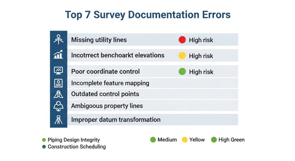
Coordinate Control and Grid Alignment
Coordinate control is the backbone of 3D modeling. I have seen projects where the survey report used a local coordinate system that was not properly rotated to the plant north. When we imported this into our 3D software, the entire plant was skewed by 2.5 degrees. This error propagates through every pipe spool drawing, making field fit-up impossible.
Field Warning: The “Missing Utility” Trap
Never assume that a survey report includes all underground utilities. I have encountered instances where abandoned fiber optic lines or legacy drainage pipes were omitted, leading to catastrophic clashes during foundation excavation. Always mandate a Ground Penetrating Radar (GPR) sweep in addition to the standard topographical survey.
Infrastructure Tie-in Levels
Tie-in points are the most critical elevations in your project. If the survey report provides an elevation for an existing nozzle that is off by even 50mm, your prefabricated piping spools will not match the field conditions. I require my team to perform a “double-check” on all tie-in elevations using a laser level, independent of the survey report’s provided data.
To calculate the required pipe slope for a gravity line, we use the formula: Slope = (Elevation Difference / Horizontal Distance) * 100. If the survey report provides an incorrect horizontal distance, your slope will be insufficient, leading to stagnant fluid and potential corrosion in process lines. Always verify the survey’s horizontal control against the site boundary markers.
Survey Report Evaluation: The systematic assessment of the benefits and inherent risks associated with relying on third-party topographical survey data for high-precision piping design.
Advantages of Rigorous Verification
- Eliminates costly field rework by identifying clashes early in the FEED stage.
- Ensures accurate pipe slope calculations for gravity-fed drainage and process lines.
- Provides a reliable basis for 3D model coordinate alignment and plant north orientation.
- Reduces the risk of foundation interference with existing underground infrastructure.
- Increases confidence in prefabricated spool accuracy, minimizing field welding.
Disadvantages of Incomplete Data
- Significant schedule delays when errors are discovered during the construction phase.
- Increased project costs due to emergency field engineering and spool re-fabrication.
- Potential for safety incidents if underground utilities are struck during excavation.
- Compromised structural integrity if pipe rack elevations do not match design assumptions.
- Loss of trust between the engineering firm and the site construction contractors.
Survey Data Application: The practical implementation of verified topographical survey data across diverse industrial sectors to ensure structural and piping design precision.
Brownfield Refinery Expansion
In brownfield projects, the density of existing underground piping is extreme. Accurate survey reports are the only way to map these legacy lines, allowing engineers to route new process piping without creating massive, costly clashes that would require shutting down active plant units.
Long-Distance Pipeline Routing
For cross-country pipelines, topographical survey reports must account for terrain changes over hundreds of kilometers. We use this data to determine the placement of anchor blocks and expansion loops, ensuring that the pipe can handle thermal expansion without buckling under the weight of the soil or terrain shifts.
Offshore Platform Tie-ins
Surveying on an offshore platform requires extreme precision due to the limited space and the movement of the structure. We rely on high-accuracy survey reports to ensure that the prefabricated piping modules fit perfectly onto the existing deck nozzles, where even a 5mm deviation can cause a major installation failure.
Greenfield Chemical Plant Layout
In greenfield sites, the survey report defines the entire plant grid. By establishing a solid coordinate control system from the start, we ensure that all pipe racks, equipment foundations, and underground drainage systems are perfectly aligned, preventing the “drift” that often occurs in large-scale industrial construction.
In my two decades of piping design, I have observed that the most significant project delays often stem from a fundamental misunderstanding of survey tolerances. When we integrate topographical survey reports into our 3D models, we must ensure that the data aligns with the specific requirements of the ASCE standards for utility engineering. If the survey data lacks the necessary precision, the resulting piping stress analysis or pipe rack foundation design will inevitably fail during the construction phase, leading to expensive field modifications.
The following table outlines the critical accuracy requirements for various site features. These values represent the maximum allowable deviation for industrial facility layouts. Engineers must cross-reference these values against the project-specific API guidelines to ensure that the survey deliverables are fit for purpose. Always verify that the surveyor has applied the correct coordinate system, such as NAD83 or WGS84, before proceeding with any site-wide piping routing or equipment placement.
| Feature Type | Horizontal Tolerance | Vertical Tolerance | Standard Reference |
|---|---|---|---|
| Primary Benchmarks | +/- 5mm | +/- 2mm | ASCE 38-02 |
| Underground Utilities | +/- 150mm | +/- 100mm | ASCE 38-02 (QL-B) |
| Equipment Foundations | +/- 10mm | +/- 5mm | ACI 117 |
| Pipe Rack Centerlines | +/- 20mm | +/- 10mm | AISC 303 |
Effective project management requires a clear understanding of the technical entities involved in topographical survey reports. When reviewing these documents, I categorize data points based on their impact on the piping design lifecycle. This matrix serves as a quick-reference guide for identifying which standards govern specific site elements, ensuring that our team maintains consistency across all engineering disciplines.
By mapping these entities, we can quickly identify gaps in the survey scope. For instance, if a report lacks ISO-compliant coordinate metadata, we immediately flag it for revision. This proactive approach prevents the common pitfall of “data drift,” where multiple sub-contractors use conflicting site datums, ultimately causing catastrophic alignment issues during the installation of large-bore piping systems or modular equipment skids.
| Entity | Acronym | Primary Standard |
|---|---|---|
| Geodetic Datum | GDA | ISO 19111 |
| Subsurface Utility Engineering | SUE | ASCE 38-02 |
| Digital Elevation Model | DEM | USGS Standards |
| Global Navigation Satellite System | GNSS | RTCM 10403 |
Before I approve any topographical survey report for use in our piping design software, I perform a rigorous verification process. This checklist is designed to catch the most common errors that lead to field rework. Use this as a mandatory gate-check for all incoming survey deliverables to ensure your project remains on schedule and within budget.
-
Benchmark Validation: Confirm that at least three permanent, independent benchmarks are clearly marked and verified against the project datum. -
Utility Verification: Ensure all underground utilities are classified by Quality Level (QL-A to QL-D) per ASCE 38-02. -
Coordinate Control: Verify that the survey grid matches the project site coordinate system exactly, including rotation and scale factors. -
Infrastructure Tie-ins: Check that all existing pipe rack elevations and nozzle heights are surveyed to within 5mm accuracy. -
Deliverable Completeness: Confirm that the CAD files include all necessary layers, line types, and metadata as defined in the project BIM execution plan.
If any of these items fail, the report must be returned to the surveyor for correction. Never assume that a “certified” stamp guarantees accuracy; always perform a spot-check of known site features to validate the survey data against your own field observations.
The Problem: Misaligned Pipe Rack Foundation
A major refinery expansion project faced a critical delay when the pre-fabricated pipe rack modules failed to align with the cast-in-place concrete foundations.
- Surveyor used an outdated local datum instead of the project-wide site grid.
- Missing utility survey led to a conflict with an existing high-pressure fire water line.
- Lack of clear benchmark identification caused a 150mm vertical error across the rack length.
The Outcome: Corrective Measures and Lessons Learned
The project team implemented a comprehensive re-survey and adjusted the design to accommodate the existing utility constraints.
- Established a new, verified site control network with redundant benchmarks.
- Implemented a mandatory “Survey Validation” sign-off for all civil and piping leads.
- Reduced future rework costs by 40% through stricter adherence to ASCE 38-02 standards.
My recommendation is to always perform a “pre-survey” audit. Before the surveyor mobilizes, provide them with a clear, written scope of work that explicitly defines the required coordinate system, accuracy tolerances, and the specific infrastructure tie-in points that are critical to your piping design.
Frequently Asked Engineering Questions
How do I verify survey benchmark accuracy?
- Perform a check-leveling run between the site benchmarks.
- Ensure the closure error is within the limits defined by NOAA standards.
- Document all discrepancies in a formal RFI to the survey firm.
What is the importance of SUE Quality Levels?
- Level D is the lowest, based on existing records.
- Level A is the highest, requiring physical exposure via vacuum excavation.
- Always specify Level B or higher for areas where new pipe racks will be installed to avoid costly utility strikes.
How do coordinate systems affect piping design?
- Ensure the survey uses the correct projection (e.g., UTM or State Plane).
- Verify the scale factor is applied correctly to avoid distance errors over long pipe runs.
- Always confirm the datum (e.g., NAD83 vs. WGS84) with the project surveyor before starting the model.
What are the risks of missing infrastructure tie-ins?
- Inaccurate nozzle heights lead to excessive pipe stress.
- Incorrect flange orientation can prevent proper bolt-up.
- Always require the surveyor to provide a detailed “tie-in report” with photos and precise measurements for every connection point.
How do I handle insufficient survey deliverables?
- Issue a formal request for additional information (RFI).
- Clearly define the missing data points and the required accuracy.
- Hold the survey payment until the deliverables meet the project’s technical specifications.
Why is site survey accuracy critical for piping?
- Inaccurate survey data leads to pipe rack misalignment.
- Poor elevation data causes drainage issues in gravity-fed lines.
- High-accuracy surveys are the foundation of a successful, safe, and cost-effective piping installation.
Complete Course on
Piping Engineering
Check Now
Key Features
- 125+ Hours Content
- 500+ Recorded Lectures
- 20+ Years Exp.
- Lifetime Access
Coverage
- Codes & Standards
- Layouts & Design
- Material Eng.
- Stress Analysis

📚 Recommended Resources: topographical survey reports
Read these Guides
- 📄 Mastering Topographical Survey Reports for Precision Piping Engineering Design
- 📄 How to Read and Interpret Geotechnical Investigation Reports for Engineers
- 📄 Essential Survey Instruments Used in Geotechnical Investigations for Site Analysis
- 📄 Geotechnical and Topographical Surveys: A Complete Guide for Engineers