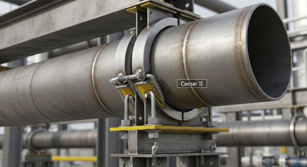
Modeling of Sway Braces in Caesar II for Stress Analysis
In my two decades of piping stress analysis, I have observed that the most common point of failure in complex piping systems is not the pipe itself, but the improper modeling of dynamic restraints. When we talk about the modeling of sway braces in Caesar II, we are essentially bridging the gap between static flexibility analysis and dynamic load management.
A sway brace is not a rigid anchor; it is a spring-loaded device designed to control pipe movement while allowing for thermal expansion. If you model these as rigid restraints, you will inevitably generate false stress reports and potentially cause the field installation to fail under actual operating conditions. This guide provides the technical framework to correctly input these components into your software environment.
Key Takeaways for Stress Engineers
- Understand the difference between rigid, spring, and sway brace stiffness inputs.
- Learn to calculate the effective spring rate for dynamic load cases.
- Master the integration of thermal displacement vectors into brace settings.
- Ensure compliance with ASME B31.1 and ASME B31.3 standards.
Technical Deep-Dive: Modeling of Sway Braces in Caesar II
Sway Brace Stiffness Definition: The accurate modeling of sway braces in Caesar II requires the engineer to define the device as a spring restraint with specific stiffness values derived from the manufacturer’s catalog data. Unlike a standard constant spring hanger, a sway brace provides resistance in both directions along the axis of the brace, necessitating a careful review of the stiffness matrix.
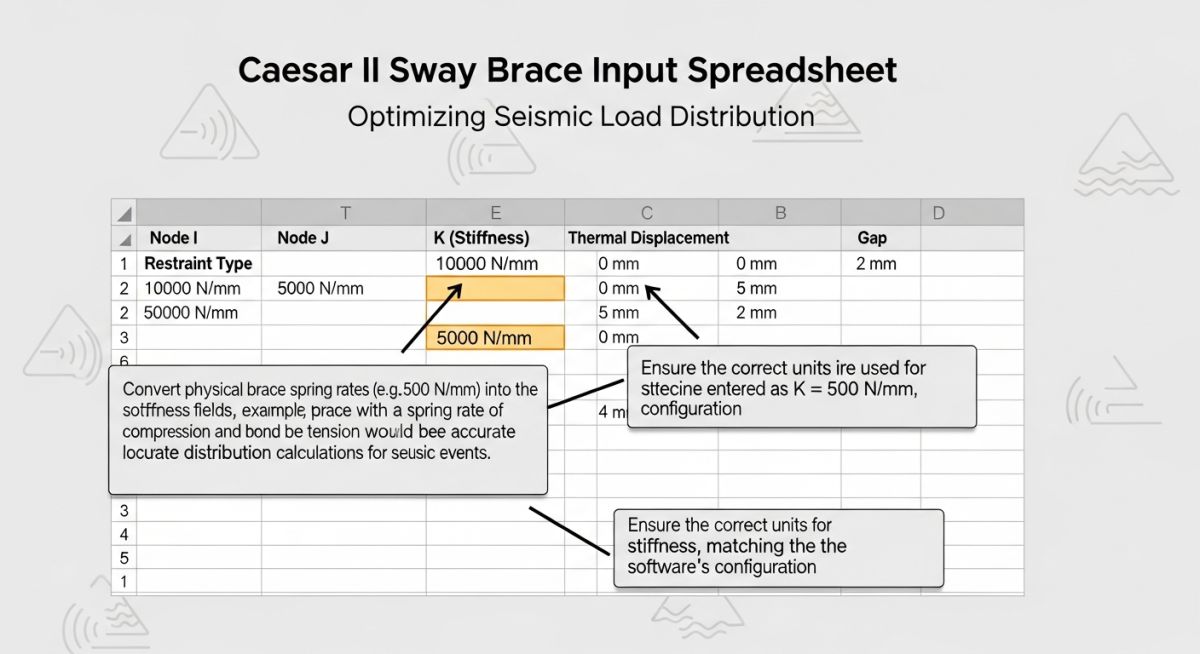
To begin, you must identify the operating temperature and the expected thermal displacement at the node point. In Caesar II, you should utilize the ‘Restraint’ tab to define the stiffness (K) in the global X, Y, and Z directions. If the sway brace is installed at an angle, you must resolve the stiffness vector into its global components using the direction cosines of the brace orientation.
When modeling, consider the following calculation steps for the effective stiffness:
- Determine the required load capacity based on the dynamic analysis (e.g., wind or seismic loads).
- Extract the spring constant (K) from the manufacturer’s data sheet, typically provided in N/mm or lb/in.
- Calculate the global stiffness components: Kx = K * cos(alpha), Ky = K * cos(beta), Kz = K * cos(gamma).
- Input these values into the Caesar II restraint dialog box, ensuring the ‘Gap’ and ‘Friction’ parameters are set to zero unless the specific design requires a dead-band.
For thermal expansion, the sway brace must be modeled to allow for the pipe’s movement. If the brace is too stiff, it will act as a rigid restraint, creating high thermal stresses. If it is too soft, it will fail to provide the necessary dynamic support. I recommend running a ‘Cold’ and ‘Hot’ case analysis to verify that the brace remains within its operational travel range throughout the entire thermal cycle.
Finally, always check the ASME B31.3 code compliance for the support structure. The reaction forces calculated by Caesar II at the sway brace node must be compared against the structural steel capacity to ensure that the support attachment does not induce local wall thinning or stress concentrations in the pipe wall.
Sway Brace Performance Metrics: The implementation of sway braces offers a balanced approach to dynamic load management, though it introduces specific complexities in modeling and maintenance that must be accounted for during the design phase.
Advantages
- Provides effective control of pipe vibration and sway without restricting thermal growth.
- Reduces the magnitude of dynamic loads transferred to sensitive equipment nozzles.
- Allows for field adjustment of the spring preload to match actual site conditions.
- Minimizes the risk of fatigue failure in long-span piping runs subject to wind.
- Offers a cost-effective alternative to rigid structural bracing in congested pipe racks.
Disadvantages
- Requires periodic inspection and maintenance to ensure spring integrity.
- Increases the complexity of the stress model, requiring precise stiffness inputs.
- Potential for ‘lock-up’ if the thermal displacement exceeds the design travel range.
- Higher initial procurement and installation costs compared to simple guides.
- Susceptible to environmental degradation if not properly coated for the site climate.
Industrial Support Integration: Sway braces are utilized across diverse sectors to manage dynamic forces while maintaining system flexibility, as detailed in the following industry-specific applications.
High-Pressure Steam Distribution
In power generation facilities, steam lines experience significant thermal expansion and high-velocity flow-induced vibration. Sway braces are installed at critical elbows to dampen these oscillations, ensuring that the piping remains within the allowable stress limits defined by ASME B31.1.
Offshore Oil and Gas Platforms
The dynamic environment of offshore platforms requires robust support systems that can handle both wave-induced motion and process-related vibrations. Sway braces provide the necessary flexibility to accommodate the structural deflection of the platform while keeping the piping system stable under extreme weather conditions.
Cryogenic Liquefied Natural Gas (LNG) Plants
LNG piping systems operate at extremely low temperatures, leading to significant contraction and expansion cycles. Sway braces are used to manage the movement of these lines, preventing the buildup of excessive thermal stresses that could lead to brittle fracture or flange leakage at connection points.
Chemical Processing Plant Feedstock Lines
In chemical plants, long-run feedstock lines are often subject to wind-induced vortex shedding. By strategically placing sway braces, engineers can shift the natural frequency of the piping system, effectively mitigating the risk of resonance and ensuring long-term structural integrity of the process piping network.
When configuring sway braces in Caesar II, the accuracy of your input parameters directly dictates the validity of the structural load distribution. Sway braces are essentially rigid or spring-based restraints designed to limit lateral movement during dynamic events like wind, seismic activity, or fluid hammer. Unlike simple rigid struts, these components often require specific stiffness values that must be derived from the manufacturer’s data sheets or calculated based on the effective length of the brace assembly.
The following table outlines the typical stiffness ranges and load capacities I encounter during standard refinery piping stress analysis. It is imperative to note that the “Stiffness” value entered into the Caesar II restraint dialog must account for the combined flexibility of the pipe clamp, the brace member, and the structural attachment point. If you ignore the flexibility of the structural steel interface, your model will likely overestimate the restraint’s effectiveness, leading to non-conservative stress results at the nozzle or branch connections.
| Brace Type | Typical Stiffness (N/mm) | Primary Application | Code Reference |
|---|---|---|---|
| Rigid Strut | 1.0E+06 to 5.0E+06 | High-frequency vibration control | ASME B31.3 |
| Snubber (Hydraulic) | Variable (Dynamic) | Seismic/Transient shock loading | ASME Section III |
| Spring Sway Brace | 500 to 5,000 | Thermal expansion accommodation | MSS SP-58 |
Always verify that the stiffness values provided by the vendor are consistent with the units defined in your Caesar II configuration file. A common error involves mixing Imperial and Metric stiffness units, which can result in a model that behaves as if it were infinitely rigid, masking potential piping failures during thermal expansion cycles.
To effectively manage the complexity of sway brace integration, engineers must map physical hardware components to their corresponding mathematical representations within the software. This matrix serves as a bridge between the physical piping layout and the analytical model, ensuring that every restraint is correctly categorized by its functional intent and mechanical behavior.
The mapping below highlights the critical entities that influence the global stiffness matrix of your piping system. By standardizing these inputs, you reduce the risk of modeling errors that often arise when transitioning from a 3D CAD model to a stress analysis environment. Pay close attention to the “Degrees of Freedom” column, as this determines how the software interprets the restraint’s interaction with the pipe’s thermal growth.
| Entity | Caesar II Input | DOF Constraint | Standard |
|---|---|---|---|
| Sway Brace | Restraint (K) | Lateral (X, Y, or Z) | MSS SP-58 |
| Structural Steel | Rigid Element | Fixed/Pinned | AISC 360 |
| Pipe Clamp | Rigid/Flexible Link | Radial/Axial | ASME B31.1 |
Utilizing this matrix during the initial setup phase of your Caesar II project ensures that the boundary conditions are correctly defined. If you are working on a brownfield project, always cross-reference these entities with the existing structural drawings to confirm that the assumed stiffness values are representative of the actual installed hardware.
Before finalizing your stress analysis report, you must perform a rigorous verification of the sway brace configurations. In my experience, the most common cause of model-to-site discrepancies is the failure to account for the actual orientation of the sway brace relative to the pipe centerline. Use this checklist to ensure your model is robust and compliant with industry standards.
- ✓ Verify that the sway brace stiffness (K) is calculated based on the total assembly length, including the structural attachment.
- ✓ Confirm that the restraint direction in Caesar II matches the physical orientation of the brace on the isometric drawing.
- ✓ Check for potential interference between the sway brace and adjacent piping or structural steel members during thermal expansion.
- ✓ Validate that the load capacity of the selected sway brace exceeds the maximum calculated dynamic load from the Caesar II output report.
- ✓ Ensure that the support location is not creating an unintended moment on the pipe branch connection, as per ASME B31.3 guidelines.
- ✓ Document the “as-modeled” stiffness values in the project stress analysis summary for future maintenance and audit purposes.
When performing site verification, pay close attention to the “cold” vs “hot” settings of the sway braces. If the brace is designed to be neutral at operating temperature, ensure that the Caesar II model reflects the correct thermal displacement at the support point. Failure to account for this offset can lead to excessive pre-loading of the pipe, which may cause premature failure of the support hardware or the pipe wall itself.
Field Case Study: Real-World Application
The Problem: Excessive Vibration in High-Pressure Steam Line
- High-frequency vibration detected at a 12-inch steam header during startup.
- Initial stress model assumed rigid supports, ignoring the flexibility of the sway brace attachments.
- Vibration caused fatigue cracking at the small-bore branch connection near the support.
- The sway braces were found to be loose due to improper installation torque.
The Outcome: Successful Mitigation and Model Calibration
- Re-modeled the sway braces in Caesar II using actual measured stiffness values.
- Identified that the original support location was near a natural frequency node.
- Relocated the sway braces to a more effective position based on the updated modal analysis.
- Implemented a strict torque verification protocol for all sway brace hardware.
My recommendation for similar scenarios is to always perform a modal analysis in Caesar II when dealing with vibration-prone systems. By accurately modeling the sway brace stiffness, you can predict the system’s natural frequencies and avoid placing supports at locations that exacerbate the vibration. Always prioritize field measurements over theoretical assumptions when the system exhibits signs of fatigue or instability.
Frequently Asked Engineering Questions
How do I determine the correct stiffness for a sway brace?
- Request the spring rate or stiffness constant from the sway brace manufacturer.
- Calculate the effective stiffness of the structural steel attachment using AISC 360 methods.
- Combine these values in series using the formula for equivalent stiffness.
- Input the final value into the Caesar II restraint dialog, ensuring the units match your project specifications.
Can I use rigid restraints instead of sway braces?
- Excessive thermal stress on the pipe wall.
- Potential buckling of the restraint member itself.
- High reaction forces at the nozzle connections.
- Always evaluate the thermal displacement at the support point before choosing a rigid restraint over a flexible sway brace.
What is the impact of sway brace orientation on stress?
- Ensure the brace is oriented to resist the primary load vector.
- Account for the secondary components of force in the Caesar II model.
- Misalignment can lead to unexpected bending moments in the pipe.
- Always verify the installation angle against the design isometric.
How do I handle thermal expansion in sway brace models?
- Use the “Gap” or “Limit” features in Caesar II to allow for thermal growth.
- Ensure the sway brace does not bottom out during the thermal cycle.
- Verify that the support remains active throughout the entire operating range.
- Consult ASME B31.3 for guidance on allowable thermal movements.
What are the common pitfalls in sway brace modeling?
- Ignoring the flexibility of the structural steel.
- Incorrectly assuming the brace is perfectly rigid.
- Failing to check for interference during thermal expansion.
- Using incorrect stiffness units in the software input.
- Always perform a sensitivity analysis to see how variations in stiffness affect your stress results.
Are there specific standards for sway brace design?
- MSS SP-58 provides guidelines for pipe hangers and supports.
- ASME B31.3 covers the requirements for piping systems in process plants.
- AISC 360 is the standard for structural steel design.
- Always ensure your design complies with the specific project specifications and local building codes.
📚 Recommended Resources: Sway Braces in Caesar II
Read these Guides
- 📄 Pipe Support Sway Brace Strut Snubber Selection and Design Guide
- 📄 Piping Design Basics: Essential Elements for Industrial Plant Engineering
- 📄 Master Your Next Technical Interview With These Dynamic Pipe Stress Analysis Interview Questions
- 📄 What Causes Piping System Stresses in Industrial Plants?
Complete Course on
Piping Engineering
Check Now
Key Features
- 125+ Hours Content
- 500+ Recorded Lectures
- 20+ Years Exp.
- Lifetime Access
Coverage
- Codes & Standards
- Layouts & Design
- Material Eng.
- Stress Analysis
