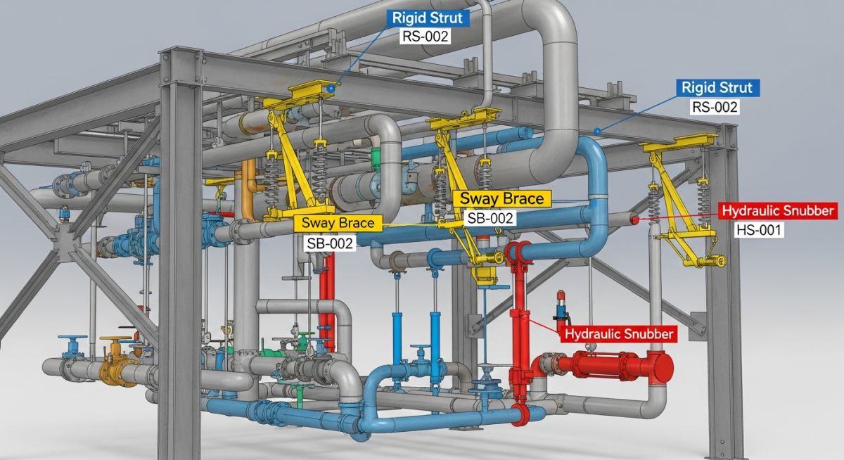
Pipe Support Sway Brace Strut Snubber Selection and Design Guide
In my 20-plus years of troubleshooting high-energy piping systems, I have seen my share of catastrophic support failures. I still remember a high-pressure steam line bypass system at a combined-cycle plant that nearly tore itself off the rack. The culprit? A rigid strut installed where a dynamic snubber was desperately needed. The piping designer had overlooked the rapid thermal expansion of the line during startup, causing the rigid strut to act as an unintended anchor. This buckled the structural steel and cracked the valve nozzle.
Managing the delicate balance between thermal flexibility and structural rigidity is one of the greatest challenges in piping engineering. We must design systems that are flexible enough to expand without overstressing equipment nozzles, yet rigid enough to withstand seismic events, water hammer, and flow-induced vibration. This is where the specialized triad of the sway brace, rigid strut, and dynamic snubber comes into play.
Key Engineering Takeaways
- Understand the distinct mechanical behaviors of sway braces, rigid struts, and snubbers.
- Learn how to apply ASME B31.3 and MSS SP-58 design boundaries to dynamic restraints.
- Master the calculation steps for sizing struts and determining snubber travel limits.
- Identify critical field installation errors that lead to piping fatigue and nozzle failures.
Understanding Pipe Support Sway Brace Strut Snubber Selection Criteria
Dynamic Piping Restraints: The selection of pipe support sway brace strut snubber components is governed by ASME B31.3 and ASME B31.1 to control thermal expansion, structural vibration, and transient dynamic loads like water hammer.
To select the correct restraint, we must first analyze the nature of the load and the frequency of the movement. Piping displacements are broadly categorized into slow thermal movements (quasi-static) and rapid dynamic events (transient or steady-state vibrations).
1. Sway Braces: The Vibration Dampeners
A sway brace is a spring-loaded device designed to control low-amplitude, high-frequency piping vibration. It consists of a single spring pre-compressed between two limit stops in a housing. When the pipe attempts to move, the sway brace opposes the movement with a force proportional to the displacement.
The governing equation for a sway brace force is:
Where F is the total resisting force, F_preload is the initial pre-compression force of the spring, k is the spring rate, and x is the piping displacement from the neutral position. Because the sway brace exerts a continuous force, it must be factored into the piping stress analysis as an added spring load. It does not lock up; rather, it acts as a stiff spring that dampens structural oscillations.
2. Rigid Struts: The Absolute Restraints
A rigid strut is a pin-to-pin structural link that provides positive, rigid restraint along its longitudinal axis. It allows angular rotation at its end attachments (typically up to plus or minus 4 degrees of swing) but permits zero axial displacement.
When designing rigid struts, we must evaluate them as structural columns subject to tension and compression. The critical buckling load of a strut is calculated using Euler’s buckling formula:
Where P_cr is the critical buckling load, E is the modulus of elasticity of the strut material, I is the minimum moment of inertia of the strut cross-section, L is the unbraced length of the strut, and K is the effective length factor (equal to 1.0 for pinned-pinned ends). Manufacturers design these components with a safety factor of at least 3.0 against buckling, in compliance with MSS SP-58.
3. Snubbers: The Velocity-Sensitive Shock Absorbers
Snubbers are dynamic restraints designed to allow free thermal movement of the piping during normal operation but lock up instantly during dynamic events like earthquakes, turbine trips, or safety valve discharges. They act as a rigid support only when subjected to high-velocity or high-acceleration inputs.
There are two primary types of snubbers:
- Hydraulic Snubbers: These utilize a piston moving through a fluid chamber. During slow thermal movement, fluid passes freely through a bypass valve. When a high-velocity transient occurs, the control valve closes, trapping the fluid and locking the piston. The lock-up velocity typically ranges from 1 to 10 inches per minute (0.4 to 4.2 mm/s).
- Mechanical Snubbers: These use a ball screw and a rotating inertial mass (flywheel). Rapid acceleration of the pipe causes the flywheel to rotate rapidly, engaging a braking mechanism that limits further acceleration. They are highly sensitive to acceleration thresholds, typically locking up at 0.02g.
Never paint the piston shaft of a hydraulic or mechanical snubber. Paint accumulation on the polished shaft destroys the synthetic seals during thermal cycles, leading to fluid loss in hydraulic units or mechanical binding in mechanical units. This renders the dynamic restraint completely useless and can cause catastrophic piping overstress.
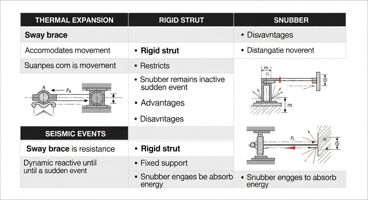
| Restraint Type | Primary Function | Thermal Movement Allowed | Dynamic Load Response | Standard Compliance |
|---|---|---|---|---|
| Sway Brace | Vibration dampening and control | Yes (with proportional resistance force) | Dampens low-frequency oscillations | MSS SP-58 Type 50 |
| Rigid Strut | Rigid axial restraint | No (zero axial displacement allowed) | Acts as a rigid structural member | MSS SP-58 Type 8 |
| Hydraulic Snubber | Shock absorption (velocity sensitive) | Yes (unrestricted at low velocity) | Locks up to form a rigid support | ASME Section III / MSS SP-58 |
| Mechanical Snubber | Shock absorption (acceleration sensitive) | Yes (unrestricted at low acceleration) | Locks up via inertial braking | ASME Section III / MSS SP-58 |
| Entity / Acronym | Physical Parameter | Typical Value Range | Reference Standard |
|---|---|---|---|
| Sway Brace Preload | Initial force (F_preload) | 50 to 1800 lbs (0.22 to 8.0 kN) | MSS SP-58 |
| Strut Swing Angle | Angular misalignment tolerance | Plus or minus 4 degrees | ASME B31.3 |
| Snubber Drag Force | Frictional resistance during thermal cycle | Less than 1% to 2% of rated load | ASME B31.1 |
| Snubber Lock-up Velocity | Activation threshold velocity | 1 to 10 in/min (0.4 to 4.2 mm/s) | ASME Section III OM |
Designing Systems with Pipe Support Sway Brace Strut Snubber Components
Piping System Design: Integrating dynamic restraints requires rigorous stress analysis using software like CAESAR II to verify that nozzle loads and pipe stresses remain within ASME B31.3 limits.
Before releasing a piping design for construction, the stress engineer must verify that every dynamic restraint is correctly modeled and specified. Field verification is the final line of defense against catastrophic piping failures.
Site Verification & Design Checklist
-
Verify Strut Swing Angles: Ensure the total thermal displacement of the pipe does not cause the rigid strut to swing more than 4 degrees from its vertical or horizontal axis. Exceeding this limit introduces severe bending moments into the strut assembly.
-
Confirm Snubber Cold and Hot Settings: Check that the snubber piston is positioned such that it has sufficient travel in both directions. The formula for snubber travel margin is:Total Travel = (Thermal Displacement * 1.2) + 0.5 inches
This ensures the piston does not bottom out or pull out completely during thermal transients.
-
Inspect Sway Brace Preload: Verify that the sway brace spring is pre-compressed to the design load specified in the stress isometric. An uncompressed sway brace will not provide immediate resistance to low-amplitude vibrations.
-
Check Structural Attachment Rigidity: Dynamic restraints are only as good as the steel they are anchored to. Ensure the supporting structural steel is designed to withstand the dynamic impact loads (often 2.0 times the static load for snubbers) without excessive deflection.
-
Remove Shipping Pins: Ensure all temporary travel locking pins or shipping straps are removed from snubbers and sway braces prior to hydrotesting and commissioning.
Field Case Study: Real-World Application
The Problem: Severe Vibration and Fatigue Cracking
At a combined-cycle power plant, a 16-inch high-pressure steam line experienced severe, low-frequency vibration (approximately 4 to 6 Hz) during turbine bypass operations. The original design utilized rigid struts to anchor the line. However, the rigid struts restricted the thermal expansion of the line during startup, causing the piping stress to exceed ASME B31.1 allowable limits and resulting in a fatigue crack at a nearby branch connection.
The Solution: Dynamic Restraint Redesign
I was called in to perform a root-cause analysis. We remodeled the piping system in CAESAR II and replaced the rigid struts with a combination of hydraulic snubbers and a pre-loaded sway brace. The hydraulic snubbers allowed the pipe to expand slowly (0.1 inches per minute) during startup without resistance. During the bypass valve opening transient, the snubbers locked up instantly, acting as rigid supports to absorb the high-energy shock. The sway brace was tuned to dampen the steady-state 5 Hz vibration.
Direct Recommendation: When dealing with high-energy piping systems subject to both thermal expansion and dynamic transients, never rely solely on rigid supports. Always perform a dynamic modal analysis to identify the natural frequencies of the system and strategically place snubbers and sway braces to control vibration without restricting thermal growth.
Frequently Asked Engineering Questions
What is the primary difference between a sway brace and a rigid strut?
How do hydraulic and mechanical snubbers differ in operation?
When should I use a sway brace instead of a snubber?
What are the ASME B31.3 requirements for dynamic restraints?
How do you calculate the cold and hot settings for a snubber?
What are the common failure modes of hydraulic snubbers?
===
Complete Course on
Piping Engineering
Check Now
Key Features
- 125+ Hours Content
- 500+ Recorded Lectures
- 20+ Years Exp.
- Lifetime Access
Coverage
- Codes & Standards
- Layouts & Design
- Material Eng.
- Stress Analysis
