Preventing Pipeline Corrosion Under Pipe Supports With SmartPads System
In my 20+ years of managing pipeline integrity across major oil, gas, and petrochemical facilities, few sights fill me with as much dread as lifting an operating pipeline during a turnaround only to discover deep, localized pitting at the support saddle. It is a classic, silent killer. The interface between a heavy steel pipe and its structural support is a natural trap for moisture, atmospheric salts, and industrial pollutants. Traditional mitigation methods—such as simple painting, neoprene wraps, or welded wear plates—often fail prematurely, introducing new stress concentrations or trapping water even more effectively.
This is where the SmartPads system has completely changed the game for asset owners. By utilizing high-performance, non-metallic composite wear pads cold-bonded directly to the pipe surface, we can eliminate the crevice entirely, isolate the pipeline electrically from structural steel, and absorb the mechanical wear caused by thermal expansion. Let us dive deep into how this technology works, the engineering calculations behind its application, and how you can implement it to protect your critical infrastructure.
Key Engineering Takeaways
- Crevice Elimination: Cold-bonding composite pads directly to the pipe surface prevents water ingress at the support interface.
- Electrical Isolation: Non-metallic materials break the galvanic corrosion cell between the pipeline and structural steel supports.
- Stress Distribution: High compressive strength composites distribute heavy radial loads without inducing localized shear stresses.
- Zero Hot Work: Cold-bonding eliminates the need for welding, avoiding heat-affected zones (HAZ) and allowing live-line installation.
Complete Course on
Piping Engineering
Check Now
Key Features
- 125+ Hours Content
- 500+ Recorded Lectures
- 20+ Years Exp.
- Lifetime Access
Coverage
- Codes & Standards
- Layouts & Design
- Material Eng.
- Stress Analysis
How Pipeline Corrosion Under Pipe Supports Occurs
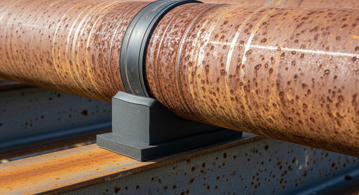
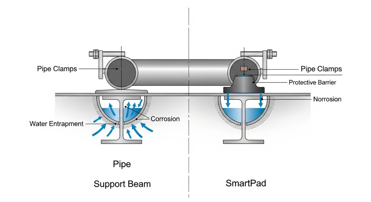
To understand why the SmartPads system is so effective, we must first analyze the physics of the failure. When a bare or painted steel pipe rests directly on an I-beam, channel, or saddle support, a micro-crevice is formed. Rainwater, condensation, or washdown fluids are drawn into this crevice via capillary action. Once trapped, the water cannot easily evaporate.
Over time, oxygen within the trapped water is depleted, while the water outside the crevice remains oxygen-rich. This differential aeration creates an electrochemical cell: the oxygen-starved steel inside the crevice becomes the anode (corroding rapidly), while the oxygen-rich steel outside becomes the cathode. This process is further accelerated by mechanical fretting. As the pipeline expands and contracts due to thermal cycles, it rubs against the support, scraping away protective paint coatings and exposing fresh, highly reactive steel to the corrosive electrolyte.
In my field audits, I frequently encounter operators who have placed loose neoprene or rubber sheets under their pipes. This is a dangerous practice. Unbonded pads act as water-retaining sponges. Capillary action draws moisture between the rubber and the pipe, where it remains trapped indefinitely, accelerating localized pitting while hiding the damage from visual inspection.
Engineering Calculations: Bearing and Shear Stress Limits
When designing a composite wear pad system, we must ensure that the pad can withstand both the static radial load of the filled pipeline and the dynamic axial shear forces generated during thermal expansion.
The localized bearing stress (S_b) on the composite pad is calculated using the radial support reaction force (P) and the projected contact area of the pad:
Where:
• P = Radial support reaction force (Newtons)
• D_o = Outer diameter of the pipeline (mm)
• W_p = Axial width of the SmartPad (mm)
Let us look at a practical field example. Consider a 24-inch (609.6 mm) gas transmission pipeline with a wall thickness of 12.7 mm, operating at 80 bar. The calculated support reaction force (P) at a critical hanger location is 45,000 Newtons. If we specify a SmartPad with an axial width (W_p) of 300 mm, the bearing stress is:
High-performance composite SmartPads typically exhibit a compressive strength exceeding 150 MPa (per ASTM D695). With a calculated bearing stress of only 0.246 MPa, the safety factor against compressive failure is over 600, demonstrating the immense structural reserve of these non-metallic systems.
Next, we must evaluate the shear stress (tau) acting on the cold-bonded adhesive line during thermal expansion. The axial force (F_a) transmitted to the support due to friction is:
Where mu is the coefficient of friction between the composite pad and the steel support (typically 0.15 to 0.3). Using a conservative mu of 0.3, the axial force is:
The shear stress (tau) on the adhesive bond line is:
For a 120-degree wrap SmartPad on a 24-inch pipe, the bond area (A_bond) is approximately 191,500 mm². This yields a shear stress of:
Since high-quality structural epoxy adhesives used in the SmartPads system have a lap shear strength exceeding 15 MPa (per ASTM D1002), the bond line is incredibly secure, completely eliminating the risk of the pad slipping or shearing off during thermal cycles.
Technical Parameters for External Corrosion Prevention
To assist piping engineers in specifying the correct materials for their projects, I have compiled the critical physical and mechanical properties of the SmartPads composite system. These values represent the industry standard for high-integrity applications.
| Physical Property | Test Method | Typical Value | Engineering Significance |
|---|---|---|---|
| Compressive Strength | ASTM D695 | > 180 MPa | Prevents crushing under heavy, concentrated pipe loads. |
| Tensile Strength | ASTM D638 | > 80 MPa | Resists hoop stresses and bending moments during thermal expansion. |
| Water Absorption | ASTM D570 | < 0.1% | Prevents moisture ingress and swelling, eliminating crevice formation. |
| Dielectric Strength | ASTM D149 | > 12 kV/mm | Provides electrical isolation, preventing galvanic corrosion cells. |
| Operating Temp. Range | N/A | -50°C to +120°C | Suitable for cryogenic, ambient, and medium-temperature processes. |
The following matrix maps the SmartPads system against international pipeline standards and codes, highlighting how the technology satisfies specific regulatory and design requirements.
| Standard Reference | Core Requirement | SmartPads Compliance Mechanism | Operational Benefit |
|---|---|---|---|
| ASME B31.3 (Process Piping) | Section 321: Design of pipe supports must prevent localized overstress and wear. | Distributes radial loads uniformly over a 120-degree contact arc. | Eliminates localized stress concentrations and wall thinning. |
| ASME B31.4 (Liquid Pipelines) | Section 461: External corrosion control and monitoring of support interfaces. | Provides a sealed, non-metallic barrier that prevents water contact. | Reduces the frequency of costly ultrasonic thickness (UT) inspections. |
| NACE SP0169 (Cathodic Protection) | Section 6: Electrical isolation of pipelines from metallic structures. | High dielectric composite material prevents CP current shielding. | Optimizes cathodic protection efficiency across the entire network. |
Verifying Pipeline Corrosion Under Pipe Supports
In my experience, the success of a SmartPads installation depends entirely on the quality of surface preparation and the execution of the bonding process. Use this checklist during your next maintenance turnaround to ensure zero defects.
SmartPads Installation Quality Control Checklist
-
Pre-Inspection & Wall Thickness Verification: Perform 100% Ultrasonic Testing (UT) or Pulsed Eddy Current (PEC) at the support location to verify remaining wall thickness. Ensure the pipeline meets the minimum allowable wall thickness per ASME B31.3 before proceeding.
-
Surface Preparation (SSPC-SP11 / NACE No. 6): Power-tool clean the steel surface to a bare metal finish with a minimum anchor profile of 50 microns (2.0 mils). This profile is critical for the mechanical interlocking of the structural adhesive.
-
Contaminant Testing: Perform a salt contamination test (Sleeve method) to ensure soluble salt levels are below 5 micrograms per square centimeter. High salt levels will cause osmotic blistering beneath the adhesive.
-
Adhesive Mixing & Application: Mix the two-part structural epoxy adhesive strictly according to the manufacturer’s ratio. Apply a uniform “wet-out” coat to both the prepared steel pipe and the inner surface of the SmartPad.
-
Clamping & Squeeze-Out Verification: Position the SmartPad and apply uniform clamping pressure using heavy-duty straps. Verify that adhesive “squeeze-out” is visible along all four edges of the pad, confirming a 100% void-free bond line.
-
Cure Time & Shore D Hardness: Allow the adhesive to cure based on ambient temperature guidelines. Verify full cure using a Shore D Durometer (minimum hardness of 80) before releasing clamping straps or lowering the pipe onto the support.
Field Case Study: Real-World Application
The Problem: Severe Localized Wall Loss
During a routine integrity assessment of a 16-inch crude oil pipeline in a highly corrosive coastal refinery environment, the inspection team identified severe localized external corrosion at several I-beam supports. Ultrasonic testing revealed that the pipe wall had thinned by up to 42% in the contact zone.
Traditional repair methods, such as welding a steel wear plate, were ruled out due to the high risk of burn-through on the thinned wall, the requirement for a complete system shutdown, and the high cost of hot-work permits in a hazardous area.
The Solution: Cold-Bonded SmartPads System
The engineering team selected the SmartPads system as a cold-applied, non-intrusive repair and prevention method. Under live operating conditions, the pipeline was temporarily lifted by 5 mm using hydraulic jacks. The corroded surface was cleaned to SSPC-SP11, and the localized metal loss was filled with a high-strength, metal-rebuilding epoxy.
A 120-degree composite SmartPad was then cold-bonded directly over the repaired area. Once cured, the pipeline was lowered back onto the I-beam, with the SmartPad acting as the new wear and isolation interface.
The Long-Term Outcome
Follow-up inspections conducted 3 and 5 years post-installation showed zero further corrosion propagation. The composite pads remained perfectly bonded to the pipeline, with no signs of water ingress, cracking, or mechanical wear. By avoiding hot work and a system shutdown, the operator saved an estimated 350,000 in production downtime and labor costs, while permanently resolving the corrosion issue.
Frequently Asked Engineering Questions
How does the SmartPads system prevent crevice corrosion under pipe supports?
Can SmartPads be installed on live, operating pipelines without a shutdown?
What are the temperature limitations of the cold-bonded adhesive used in the SmartPads system?
How do SmartPads interact with cathodic protection (CP) systems?
What surface preparation standard is required before bonding SmartPads to the pipeline?
How do SmartPads compare to traditional welded wear plates in terms of stress concentration?
===

📚 Recommended Resources: pipeline corrosion under pipe supports
Read these Guides


Related posts:
![Cross-section diagram showing a steel solar pile foundation embedded in layered soil profiles for structural analysis.]()
Essential Geotechnical Pile Design Data for Utility-Scale Solar Structures
![Professional surveyor conducting Topographical Surveys for Solar Projects on a large-scale utility site with complex terrain.]()
Topographical Surveys for Solar Projects: A Technical Engineering Guide
![A geotechnical drill rig performing soil sampling on a large, open field intended for a utility-scale solar farm project.]()
Geotechnical Investigation for Solar Farms: Essential Site Design Guide
![Isometric site plan showing Utility Corridor Planning for Data Centres with color-coded power, water, and telecom infrastructure paths.]()
Utility Corridor Planning for Data Centres: A Strategic Engineering Guide
![Aerial view of a data centre site showcasing perimeter drainage systems, detention basins, and site grading for flood prevention.]()
Drainage Design Considerations for Data Centres: A Technical Guide
![Professional surveyor using a Total Station on a large data centre construction site for topographical mapping.]()
Topographical Surveys for Data Centre Projects: A Technical Guide