Mastering Pipe Weight Calculation With Our Steel Pipe Weight Chart
In my 20+ years of piping engineering, I have seen many young engineers rely blindly on software outputs without understanding the fundamental physics of pipe weight calculation. When you are designing a massive pipe rack or calculating the lifting loads for a heavy industrial module, a minor error in estimating carbon steel pipe weight can lead to structural sagging, support failures, or lifting accidents.
This guide is designed to bridge the gap between theoretical calculations and field realities. We will break down the mathematical derivations, analyze the impact of manufacturing tolerances, and provide a comprehensive steel pipe weight chart that you can use as a daily reference on-site.
- Master the exact mathematical formulas for both metric and imperial pipe weight calculations.
- Understand how mill tolerances and corrosion allowances affect actual field weights.
- Access a complete, high-contrast steel pipe weight chart covering standard schedules.
- Learn how to calculate wet (hydrotest) loads to prevent structural support failures.
Complete Course on
Piping Engineering
Check Now
Key Features
- 125+ Hours Content
- 500+ Recorded Lectures
- 20+ Years Exp.
- Lifetime Access
Coverage
- Codes & Standards
- Layouts & Design
- Material Eng.
- Stress Analysis
How to Calculate Steel Pipe Weight Mathematically
The Pipe Weight Formula: A mathematical derivation based on the hollow cylinder volume calculation that determines the nominal weight of steel pipes per unit length.
To calculate the weight of a steel pipe, we must first determine its cross-sectional area and multiply it by the density of the material. Carbon steel has a standard density of approximately 7,850 kg/m³ (0.2833 lb/in³). Let us look at the step-by-step derivation of the standard formulas used in the industry.
1. The Imperial Pipe Weight Formula (lb/ft)
In the imperial system, the formula to calculate the weight of a carbon steel pipe in pounds per foot (lb/ft) is:
Where:
- W: Nominal weight of the pipe (lb/ft)
- D: Outside diameter of the pipe (inches)
- t: Wall thickness of the pipe (inches)
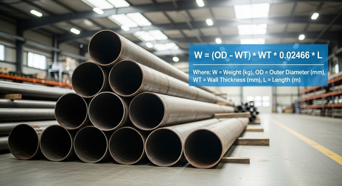
2. The Metric Pipe Weight Formula (kg/m)
In the metric system, the formula to calculate the weight of a carbon steel pipe in kilograms per meter (kg/m) is:
Where:
- W: Nominal weight of the pipe (kg/m)
- D: Outside diameter of the pipe (millimeters)
- t: Wall thickness of the pipe (millimeters)
Never design structural supports or lifting lugs based solely on the nominal weight calculated from these formulas. Under ASME B36.10M and ASTM standards, seamless steel pipes are permitted a mill tolerance wall thickness variation of up to -12.5%. Conversely, some plates used for welded pipes can have positive tolerances. Always include a structural safety margin of at least 10% to 15% in your load calculations to account for these manufacturing variances.
Understanding the Physics Behind the Constants
Many engineers ask where the constants 10.69 and 0.0246615 come from. They are not arbitrary numbers; they are derived directly from the geometry of a hollow cylinder and the density of steel.
The volume of a hollow cylinder per unit length is calculated as:
By substituting the density of carbon steel (7,850 kg/m³ or 0.2833 lb/in³) and converting the units of length and thickness, we arrive at these simplified engineering constants. This allows for rapid calculations in the field without needing to run full volumetric equations every time.
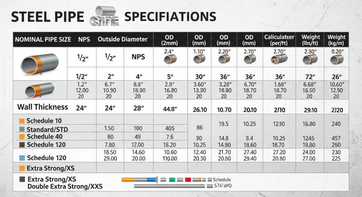
Standard Steel Pipe Weight Chart
Steel Pipe Weight Chart: A standardized reference matrix detailing nominal pipe sizes, wall thicknesses, schedules, and corresponding linear weights.
Below is a highly detailed weight chart for standard carbon steel pipes. This chart is based on the dimensions specified in ASME B36.10M. It includes both metric and imperial values for outside diameter, wall thickness, and linear weight.
| NPS (inches) | DN (mm) | Schedule | OD (mm) | Wall Thickness (mm) | Weight (kg/m) | Weight (lb/ft) |
|---|---|---|---|---|---|---|
| 1/2″ | 15 | Sch 40 (STD) | 21.3 | 2.77 | 1.27 | 0.85 |
| 1/2″ | 15 | Sch 80 (XS) | 21.3 | 3.73 | 1.62 | 1.09 |
| 1″ | 25 | Sch 40 (STD) | 33.4 | 3.38 | 2.50 | 1.68 |
| 1″ | 25 | Sch 80 (XS) | 33.4 | 4.55 | 3.24 | 2.17 |
| 2″ | 50 | Sch 40 (STD) | 60.3 | 3.91 | 5.44 | 3.65 |
| 2″ | 50 | Sch 80 (XS) | 60.3 | 5.54 | 7.48 | 5.02 |
| 4″ | 100 | Sch 40 (STD) | 114.3 | 6.02 | 16.07 | 10.79 |
| 4″ | 100 | Sch 80 (XS) | 114.3 | 8.56 | 22.32 | 14.98 |
| 6″ | 150 | Sch 40 (STD) | 168.3 | 7.11 | 28.26 | 18.97 |
| 6″ | 150 | Sch 80 (XS) | 168.3 | 10.97 | 42.56 | 28.57 |
| 8″ | 200 | Sch 40 (STD) | 219.1 | 8.18 | 42.55 | 28.55 |
| 8″ | 200 | Sch 80 (XS) | 219.1 | 12.70 | 64.64 | 43.39 |
| 12″ | 300 | Sch 40 (STD) | 323.9 | 10.31 | 79.73 | 53.52 |
| 12″ | 300 | Sch 80 (XS) | 323.9 | 17.48 | 132.04 | 88.51 |
To ensure complete compliance with international engineering standards, the following matrix maps the core technical entities, structural acronyms, and physical parameters used in pipe weight calculations.
| Technical Entity | Standard Reference | Physical Parameter | Engineering Application |
|---|---|---|---|
| ASME B36.10M | ASME B36.10M | Nominal Pipe Size (NPS) & Schedule | Standardizes dimensions and weights for welded and seamless wrought steel pipes. |
| ASTM A106 Grade B | ASTM A106 | Material Density (7,850 kg/m³) | High-temperature pressure service piping design and weight calculations. |
| Mill Tolerance | ASTM A530 | -12.5% Wall Thickness Variation | Structural load limits and minimum wall thickness verification. |
| Hydrotest Load | ASME B31.3 | Water Weight (1,000 kg/m³) | Temporary support design and structural integrity verification during testing. |
Field Quality Control Checklist
Piping Weight Verification Checklist: A structured quality control protocol used by field engineers to validate physical pipe weights against design calculations prior to structural installation.
Before executing any heavy lifts or finalizing structural pipe rack designs, field engineers must verify the physical parameters of the piping materials. Use this checklist to ensure complete accuracy on-site.
Cross-reference the physical pipe markings with the approved-for-construction (AFC) drawings and isometric sheets.
Use a calibrated ultrasonic thickness gauge to measure the actual wall thickness at four points around the pipe circumference. Compare this with the nominal thickness in the weight chart.
Check the Material Test Report (MTR) to verify the steel grade (e.g., ASTM A106 Gr. B, ASTM A333 Gr. 6). Ensure the density matches the design assumptions.
Calculate the internal volume of the pipe and add the weight of water (1,000 kg/m³) to the dry pipe weight to determine the maximum testing load.
If the pipe is insulated, add the linear weight of the insulation material (e.g., calcium silicate, polyurethane foam) and the outer metal cladding.
Ensure that all spring hangers, variable supports, and structural beams are rated for the maximum calculated wet weight plus a safety margin.
Field Case Study: Real-World Application
During a major refinery expansion project, a junior design engineer calculated the structural loads for a new 24-inch carbon steel utility line (NPS 24, Sch 40) running across a 150-meter pipe rack. The engineer calculated the structural support requirements based solely on the dry weight of the pipe (approximately 251 kg/m).
However, the engineer failed to account for the weight of the water required to fill the line during the hydrotesting phase. When the line was filled with water for testing, the total linear weight tripled to over 750 kg/m. This massive, unexpected load caused localized structural sagging of up to 45 mm in the supporting steel beams, threatening the integrity of adjacent high-pressure steam lines.
As the lead piping engineer, I immediately halted the hydrotest and ordered the line to be drained. We used our standard steel pipe weight chart to recalculate the exact wet load. To resolve the issue without rebuilding the entire pipe rack, we designed and installed temporary structural scaffolding and spring supports at critical mid-span locations to distribute the load during the test.
Once the hydrotest was completed successfully, the temporary supports were removed, and the permanent structural beams were retrofitted with welded steel stiffeners to increase their load-bearing capacity. This incident served as a stark reminder to the entire engineering team that hydrotest loads must always be treated as a primary design condition.
Direct Recommendation: Always maintain a clear distinction between “dry weight,” “operating weight” (including the process fluid), and “test weight” (filled with water) in your line lists and stress analysis models.
Frequently Asked Engineering Questions
How does mill tolerance affect the actual weight of a steel pipe?
What is the difference between nominal pipe weight and actual pipe weight?
Why is the density of carbon steel assumed to be 7,850 kg/m³ in weight calculations?
How do you calculate the weight of a pipe filled with water for hydrotesting?
Does the pipe weight formula apply to stainless steel and alloy steel pipes?
How does corrosion allowance impact pipe weight calculations over time?

📚 Recommended Resources: Steel Pipe Weight Chart
Read these Guides
- 📄 Overview of Lateral Buckling and Upheaval Buckling of Pipelines
- 📄 Ductile Iron Pipe Dimensions – Global Standards, Field Challenges & Engineering Insights
- 📄 Types of Steel: Complete Guide to Steel Grades, Classification & Real-World Applications
- 📄 A36 Steel: Composition, Properties, and Real-World Engineering Applications
🎥 Watch Tutorials

Related posts:
![Modern container ship utilizing green ammonia as marine fuel in a global port.]()
Green Ammonia as Marine Fuel: Engineering the Future of Shipping
![Industrial green ammonia production facility integrated with renewable energy sources.]()
Green Ammonia Economics: A Technical Guide to Industrial Scale Profitability
![Industrial PEM electrolyzer stack generating green hydrogen in a modern clean energy facility.]()
PEM Electrolyzer Explained: The Ultimate Green Hydrogen Engineering Guide
![Modern green hydrogen plant with integrated solar panels and wind turbines, showcasing renewable energy powering electrolyzer technology.]()
Designing a Green Hydrogen Plant: A Comprehensive Engineering Overview
![Industrial hydrogen compression system facility with stainless steel piping and modern compressor equipment.]()
Mastering Hydrogen Compression Systems: Engineering Design, Selection, and Safety
![Modern industrial hydrogen storage facility with high-pressure tanks and clean energy infrastructure.]()
Hydrogen Storage Technologies: A Comprehensive Engineering and Selection Guide