Table of Contents
What Are Slip Joints in Piping and How Do They Work?
In my 20 years of commissioning steam distribution networks and industrial utility lines, I have watched many young engineers struggle with thermal expansion. When a carbon steel pipe carrying superheated steam heats up, it expands with immense force. If you do not give that pipe room to grow, it will buckle, destroy its supports, or tear itself apart at the welds. While expansion loops are the traditional choice, space constraints in dense industrial plants often make them impractical. That is where the packed slip joint becomes an invaluable tool in your design arsenal.
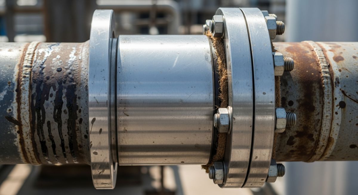
Unlike bellows-type expansion joints that rely on thin, flexible metal walls, slip joints use a rugged, heavy-wall telescoping sleeve that slides inside a larger body. This mechanical sliding action provides massive axial travel capabilities—often up to 12 inches or more in a single unit—without risking the catastrophic fatigue failures common to thin-walled bellows. However, managing these components requires a deep understanding of packing friction, pressure thrust, and strict alignment protocols.
Key Engineering Takeaways
- Massive Axial Travel: Slip joints easily handle long straight runs of piping where thermal expansion exceeds the limits of standard metallic bellows.
- Rugged Construction: The heavy-wall design resists external mechanical damage, water hammer, and torsional stresses far better than corrugated bellows.
- Maintenance Requirements: Because they rely on mechanical packing to seal the sliding sleeve, they require periodic inspection and packing adjustments to prevent leaks.
- Strict Alignment Needs: Any lateral or angular deflection will cause the internal sleeve to bind, leading to localized stress concentration and joint failure.
Complete Course on
Piping Engineering
Check Now
Key Features
- 125+ Hours Content
- 500+ Recorded Lectures
- 20+ Years Exp.
- Lifetime Access
Coverage
- Codes & Standards
- Layouts & Design
- Material Eng.
- Stress Analysis
Why Use Slip Joints in Piping Systems?
To design a safe piping system using slip joints, you must master the physics of thermal expansion and the mechanical forces acting on the joint. When a pipeline undergoes a temperature change, its change in length is calculated using the standard thermal expansion equation:
Where:
– Delta L = Total axial thermal expansion (inches or mm)
– L = Total length of the straight pipe run between anchors (feet or meters)
– alpha = Mean coefficient of thermal expansion for the pipe material (in/in/°F or mm/mm/°C)
– Delta T = Temperature difference between installation and maximum operating conditions (°F or °C)
Let us look at a real-world scenario. Suppose we have a 200-meter run of 10-inch carbon steel pipe operating at 250°C, with an installation temperature of 20°C. The mean coefficient of thermal expansion for carbon steel over this range is approximately 0.0125 mm/m°C.
Delta L = 200 * 0.0125 * 230
Delta L = 575 mm (approximately 22.6 inches)
Accommodating 575 mm of expansion using traditional expansion loops would require multiple massive loops, consuming valuable space in your pipe rack. A single double-end slip joint, or two single-end slip joints placed strategically, can handle this movement easily within the run’s native footprint.
Calculating System Forces and Anchor Loads
One of the most common mistakes I see in the field is underestimating the loads acting on the main anchors. When you install a slip joint, the pipe is essentially cut in half. The internal pressure of the fluid acts directly on the cross-sectional area of the slip sleeve, trying to blow the joint apart. This is known as the pressure thrust force.
The total force (F_total) that your main anchors must withstand is the sum of the pressure thrust force (F_p) and the packing friction force (F_f):
Where:
– F_p = P * A (Internal pressure multiplied by the effective cross-sectional area of the slip sleeve)
– F_f = Packing friction force (typically provided by the manufacturer, based on packing tightness and sleeve diameter)
For a 10-inch pipe operating at 300 PSI, the effective area (A) is approximately 78.5 square inches. The pressure thrust force alone is:
If your structural team designs the anchors assuming only simple thermal friction, those anchors will fail during hydrostatic testing. You must design your structural steel to handle this massive pressure thrust in compliance with ASME B31.3 and ASME B31.1.
Slip joints are strictly designed for axial (straight-line) movement. They have zero capability to absorb lateral offset, angular rotation, or torsional twisting. If the piping system experiences even minor lateral movement, the sliding sleeve will bind against the stuffing box. This binding stops all thermal movement, transferring massive structural loads back into the piping system, which inevitably leads to flange leaks, pipe buckling, or catastrophic anchor failure.
Selecting the correct slip joint requires matching the system’s operating temperature, pressure, and fluid medium with the appropriate packing material and sleeve design. The table below outlines standard industrial selection parameters.
| Nominal Pipe Size (NPS) | Max Axial Travel (Single End) | Max Operating Pressure | Recommended Packing | Typical Fluid Service |
|---|---|---|---|---|
| 2″ to 6″ | 4 to 8 inches | 300 PSI (20.7 bar) | PTFE / Graphite Filament | Low-Pressure Steam, Condensate |
| 8″ to 16″ | 8 to 12 inches | 400 PSI (27.6 bar) | Flexible Graphite with Inconel Wire | High-Pressure Steam, Hot Water |
| 18″ to 24″ | 12 to 18 inches | 250 PSI (17.2 bar) | Molded Graphite Rings | District Heating, Utility Steam |
| 26″ and Above | Custom (Up to 24″) | 150 PSI (10.3 bar) | Injectable Packing Compounds | Water Transmission, Low-Temp Gas |
To ensure seamless communication between piping designers, structural engineers, and field installers, use this technical mapping matrix to identify key components, their acronyms, and governing standards.
| Technical Entity | Structural Acronym | Physical Parameter | Governing Standard Reference |
|---|---|---|---|
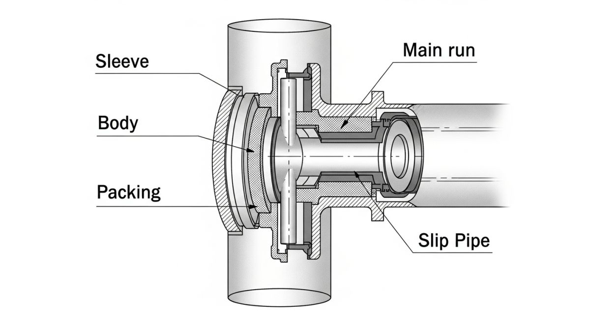
| Slip Sleeve (Inner Pipe) | SSV | Wall Thickness, Surface Finish (Ra) | ASME B31.3 Chapter II |
| Stuffing Box (Outer Body) | SBX | Chamber Depth, Packing Width | ASME Section VIII Div 1 |
| Compression Gland Flange | CGF | Bolt Torque, Gland Depth | ASME B16.5 / B16.47 |
| Main Anchor | MAN | Structural Load Capacity (Kips/kN) | ASCE 7 / AISC 360 |
| Alignment Guide | ALG | Guide Spacing (L1, L2, L3) | EJMA Standards |
How to Install Slip Joints in Piping Safely?
In my years of field auditing, I have found that over 80% of slip joint failures are caused by poor installation practices. If the pipe is not perfectly aligned, or if the guides are placed too far from the joint, the sleeve will bind, causing localized stress concentration. Use this checklist on-site before commissioning any system containing slip joints.
Pre-Commissioning Field Checklist
-
Verify Guide Spacing (L1 & L2): Ensure the first alignment guide is located within 4 pipe diameters from the slip joint, and the second guide is within 14 pipe diameters. This is critical to prevent lateral buckling.
-
Check Cold-Spring / Preset: Confirm the joint has been preset to account for the ambient temperature at the time of installation. If you install a joint fully collapsed on a freezing winter day, it will pull apart when the system cools down during a shutdown.
-
Inspect Anchor Integrity: Double-check that the main structural anchors are fully welded and bolted to the civil foundations. Never pressurize the line if temporary shipping bars are still installed or if anchors are incomplete.
-
Gland Packing Torque: Tighten the gland bolts evenly in a cross-pattern. Over-tightening will lock the sleeve and prevent sliding, while under-tightening will cause immediate packing leaks during startup.
-
Sleeve Surface Inspection: Ensure the polished sliding sleeve is completely free of weld spatter, paint, rust, or physical gouges. Any surface defect will shred the packing rings as the sleeve moves.
Field Case Study: Real-World Application
In 2018, I was called to a municipal district heating plant that was experiencing chronic failures on a 16-inch steam main running through a tight underground concrete tunnel. The original design utilized metallic bellows expansion joints. Because of the tight space, the piping team could not install adequate lateral guides.
As a result, the bellows suffered from minor lateral deflection and torsional twisting during startup cycles. Within 18 months of commissioning, three bellows suffered catastrophic fatigue cracking, filling the tunnel with high-pressure steam and shutting down heating to a major hospital complex.
We analyzed the system and determined that expansion loops were physically impossible due to the tunnel’s concrete walls. We replaced the failed bellows with heavy-duty, externally guided slip joints equipped with injectable graphite packing.
We redesigned the structural anchors at the tunnel ends to handle the 45,000 lbs of pressure thrust and packing friction. We also installed rigid pipe alignment guides directly adjacent to the slip joints to eliminate any chance of lateral binding.
The Outcome: The retrofitted system has been operating flawlessly for over eight years. The maintenance team performs a quick visual inspection every six months and injects a small amount of fresh packing compound under full system pressure once a year. The plant has experienced zero unplanned shutdowns, and the structural integrity of the tunnel piping remains perfect.
Frequently Asked Engineering Questions
What is the primary difference between a slip joint and a bellows expansion joint?
How do you calculate the pressure thrust force generated by a slip joint?
Can slip joints handle lateral or angular piping movements?
What type of packing material is recommended for high-temperature steam slip joints?
Why are pipe guides critical when installing slip joints?
How do you perform a hydrostatic test on a piping system containing slip joints?

📚 Recommended Resources: slip joints in piping
Read these Guides


Related posts:
![A mechanical sucker rod pumpjack operating in an oil field at sunset]()
What is Sucker Rod Pump System in Oil Production?
![Piping material engineer reviewing technical specifications on a tablet in an industrial plant.]()
How a Piping Material Engineer Drives Industrial Project Success
![Industrial refinery plant showing various types of static equipment]()
What is Static Equipment? Types and List of Static Equipments
![Side-by-side comparison of industrial process piping and power plant steam piping systems.]()
Differences Between ASME B31.3 and B31.1: B31.3 vs B31.1
![Large industrial steel storage tank under construction with cranes and scaffolding]()
Storage Tank Construction Method Statement: Step-by-Step Engineering Guide
![Cutaway diagram of a globe control valve highlighting the internal valve trim components]()
What is a Valve Trim? Types, Components, and Selection


