Table of Contents
What is Sheet Metal Fabrication? Sheet Metal Fabrication Process Explained
In my 20-plus years of managing heavy industrial fabrication shops, I have watched countless green engineers design parts that look beautiful on a CAD screen but are completely unbuildable on the shop floor. They forget that metal is not a digital canvas; it has grain, memory, and physical limits. When you design a custom bracket, a piping support, or a heavy-duty enclosure, you are not just drawing lines—you are instructing a press brake operator on how to fight the natural springback of a physical alloy.
Understanding the physical realities of the shop floor is what separates a theoretical designer from a seasoned field engineer. Whether we are dealing with structural carbon steel, corrosion-resistant stainless steel, or lightweight aluminum, every single cut, bend, and weld must be planned with precision. Let us dive deep into how we transform raw, flat metal sheets into high-performance industrial components.
Key Takeaways for Field Engineers
- Always design with standard material gauges to avoid custom-rolling surcharges.
- Keep your inside bend radius equal to or greater than the material thickness to prevent micro-cracking.
- Account for K-factor and bend allowance early in your CAD models to ensure accurate flat patterns.
- Select cutting methods based on material thickness and tolerance requirements to optimize production costs.
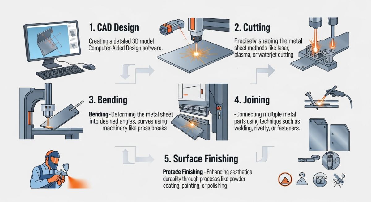
Mastering the Sheet Metal Fabrication Process Step-by-Step
Sheet Metal Fabrication Process: A multi-stage manufacturing workflow encompassing design, cutting, forming, and finishing operations to transform raw sheet stock into high-precision industrial components.
The journey from a flat sheet of metal to a finished industrial component requires a sequence of highly controlled steps. Each step must align with international standards such as ASME and ASTM to guarantee structural integrity.
Step 1: Engineering Design and Flat Pattern Development
Before any machine is turned on, we must calculate the flat pattern. When sheet metal is bent, the outer fibers stretch and the inner fibers compress. Between these two zones lies the neutral axis, which experiences zero stress. To calculate the exact flat length of a part, we use the Bend Allowance (BA) formula:
Where:
R = Inside bend radius (mm)
K = K-factor (ratio of neutral axis position to material thickness, typically 0.3 to 0.5)
T = Material thickness (mm)
A = Bend angle (degrees)
Let us look at a real-world calculation. Suppose we are bending a bracket using 3.0 mm thick ASTM A36 carbon steel. The design calls for a 90-degree bend with an inside bend radius of 3.0 mm. Using a standard K-factor of 0.43 for carbon steel on a standard press brake:
R + (K * T) = 3.0 + 1.29 = 4.29 mm
A / 180 = 90 / 180 = 0.5
BA = 3.14159 * 4.29 * 0.5 = 6.738 mm
This Bend Allowance of 6.738 mm is added to the lengths of the flat flanges to determine the exact cutting length of the raw sheet. Getting this wrong means your bolt holes will not line up during field assembly.
Step 2: Industrial Cutting Methods
Once the flat pattern is finalized, we cut the profile. In modern shops, we rely on three primary thermal and mechanical cutting methods:
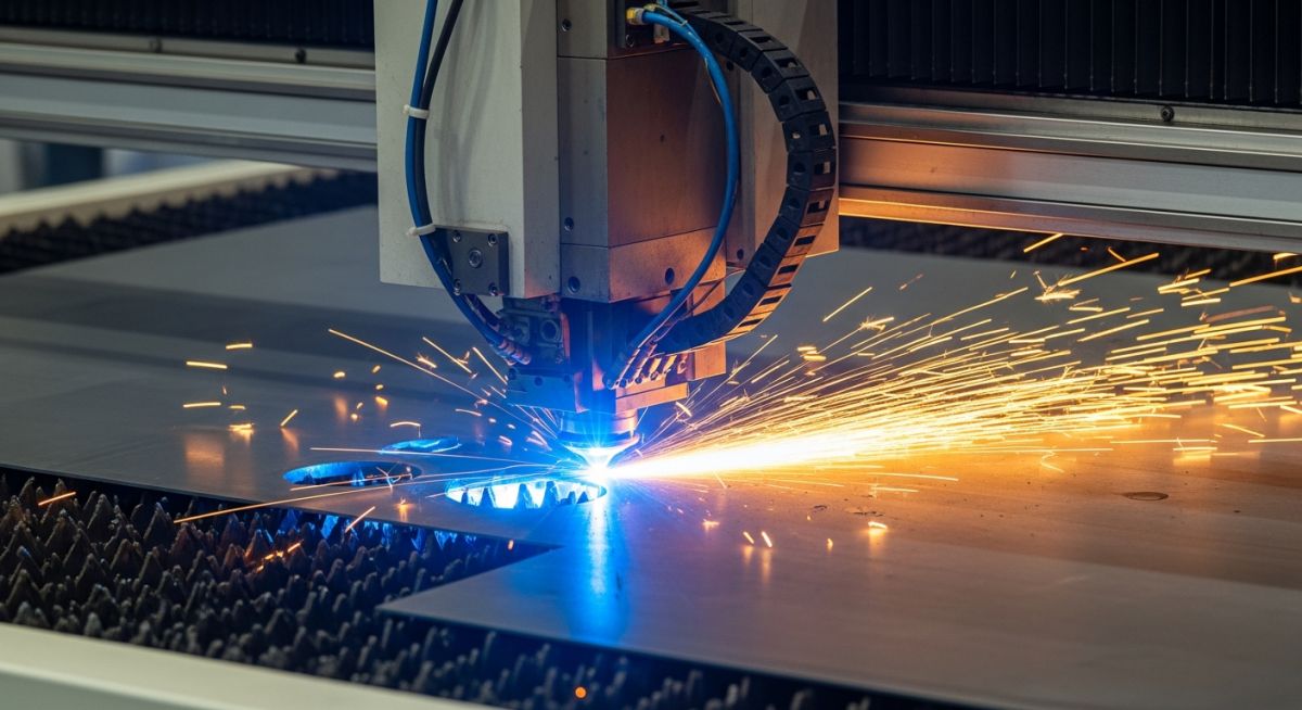
- Laser Cutting: Offers extreme precision (tolerances within +/- 0.1 mm). Ideal for complex geometries in materials up to 25 mm thick.
- Plasma Cutting: Best for thick carbon steel plates where speed is preferred over high-precision edge quality.
- Waterjet Cutting: A cold cutting process that eliminates the Heat Affected Zone (HAZ). This is critical for aerospace alloys that cannot tolerate thermal stress.
Field Warning: Watch Out for Heat Affected Zones (HAZ)
When using plasma or laser cutting on high-strength low-alloy (HSLA) steels, the intense heat alters the microstructure of the metal along the cut edge. This localized hardening can lead to micro-cracking during subsequent bending operations. If you are bending close to a cut edge, ensure the edge is ground down or cut using waterjet to preserve material ductility.
Step 3: Forming and Bending
Forming is where the flat sheet becomes a three-dimensional object. This is typically performed on a hydraulic press brake, where a punch forces the metal sheet into a V-shaped die.
During this step, we must account for springback. When the bending pressure is released, the elastic recovery of the metal causes it to open up slightly. To achieve a true 90-degree bend, the operator must over-bend the material by a few degrees, depending on the yield strength of the alloy.
Optimizing the Sheet Metal Fabrication Process Parameters
Sheet Metal Fabrication Process Parameters: The critical physical and mechanical variables, including bend radii, K-factors, and cutting tolerances, that dictate the structural integrity and dimensional accuracy of fabricated metal parts.
To ensure consistency across production runs, engineers must reference standardized material parameters. The table below outlines the recommended minimum bend radii and K-factors for common industrial alloys.
| Material Specification | Thickness Range (mm) | Recommended Min Bend Radius | Typical K-Factor Range | Applicable Standard |
|---|---|---|---|---|
| ASTM A36 Carbon Steel | 1.5 – 6.0 | 1.0 * Thickness | 0.40 – 0.45 | ASTM A36 |
| ASTM A240 Type 304 SS | 1.0 – 4.0 | 1.5 * Thickness | 0.35 – 0.40 | ASTM A240 |
| Aluminum 5052-H32 | 1.0 – 5.0 | 1.5 * Thickness | 0.40 – 0.43 | ASTM B209 |
| Aluminum 6061-T6 | 1.5 – 6.0 | 3.0 * Thickness | 0.45 – 0.48 | ASTM B209 |
This matrix maps the core technical entities, structural acronyms, and physical parameters to their respective design codes and industrial applications.
| Entity / Acronym | Physical Parameter | Design Code / Standard | Primary Industrial Application |
|---|---|---|---|
| HAZ | Heat Affected Zone Microstructure | AWS D1.1 | Structural Steel Welding & Cutting |
| K-Factor | Neutral Axis Shift Ratio | DIN 6935 | Flat Pattern Development & CAD Modeling |
| UTS | Ultimate Tensile Strength | ASTM E8/E8M | Material Selection for High-Stress Parts |
| WPS | Welding Procedure Specification | ASME Section IX | Pressure Vessel & Piping Support Joining |
Quality Control in Sheet Metal Fabrication
Sheet Metal Quality Control: The systematic verification of dimensional tolerances, material certifications, and weld integrity to ensure compliance with ASME and AWS standards.
Before any fabricated assembly leaves the shop floor or is installed at the project site, it must undergo a rigorous inspection. Use this field checklist to verify that your parts meet the required engineering specifications.
Shop Floor Inspection Checklist
-
Material Verification: Cross-reference Mill Test Reports (MTRs) with physical heat numbers stamped on the sheet metal to verify compliance with ASTM standards.
-
Dimensional Tolerance Check: Measure overall dimensions, hole diameters, and center-to-center distances using calibrated vernier calipers. Standard tolerance should be within +/- 0.5 mm unless specified otherwise.
-
Bend Angle and Radius Inspection: Use a digital protractor and radius gauges to verify that the bend angle matches the drawing and that the inside radius has not caused micro-cracking on the outer surface.
-
Weld Quality Assessment: Inspect all structural welds visually for undercut, porosity, and lack of fusion in accordance with AWS D1.1 or AWS D1.6 (for stainless steel).
-
Surface Finish and Deburring: Ensure all sharp edges are deburred to prevent injury during handling and that the surface is prepared correctly for powder coating or galvanizing.
Field Case Study: Real-World Application
Sheet Metal Engineering Case Study: An analysis of structural failure due to improper bend allowance calculations and the subsequent corrective engineering actions implemented on the shop floor.
The Problem: Cracking in Heavy-Duty Piping Support Brackets
During the construction of a petrochemical processing plant, a batch of 150 heavy-duty piping support brackets fabricated from 6.0 mm thick ASTM A240 Type 316 stainless steel began showing visible micro-cracks along the outer bend radius. The brackets were designed to support high-pressure steam lines, making any structural defect a severe safety hazard.
Upon investigation, I discovered that the design engineer had specified an inside bend radius of 3.0 mm (0.5 * Thickness) in the CAD model, which is far too tight for 6.0 mm stainless steel. The shop floor had forced the bend using a sharp punch, exceeding the material’s ultimate tensile strength on the outer fibers and causing severe stress cracking.
The Outcome: Redesign and Process Correction
I immediately halted production and implemented the following corrective actions:
- Increased the inside bend radius from 3.0 mm to 9.0 mm (1.5 * Thickness) to distribute the tensile stress across a larger area.
- Recalculated the flat pattern using a revised K-factor of 0.38, which adjusted the overall flat length of the blank by 2.4 mm to maintain the correct final dimensions.
- Introduced a mandatory dye penetrant inspection (DPI) on the first five parts of every production run to verify surface integrity along the bend lines.
The redesigned brackets passed all structural load tests and non-destructive examinations (NDE) without a single failure, saving the project from costly field modifications and schedule delays.
My recommendation to all design engineers is simple: never guess your bend parameters. Always consult with your fabrication shop’s lead operator to verify their tooling capabilities before finalizing your drawings.
Frequently Asked Engineering Questions
What is the difference between sheet metal and plate metal?
Why is the K-factor so important in the sheet metal fabrication process?
How do you prevent springback during the bending process?
Which cutting method is best for stainless steel sheet metal?
What is the minimum bend radius for structural sheet metal?
How does grain direction affect sheet metal bending?
===FAQ_BLOCK===
Complete Course on
Piping Engineering
Check Now
Key Features
- 125+ Hours Content
- 500+ Recorded Lectures
- 20+ Years Exp.
- Lifetime Access
Coverage
- Codes & Standards
- Layouts & Design
- Material Eng.
- Stress Analysis

📚 Recommended Resources: Sheet Metal Fabrication Process
Read these Guides


Related posts:
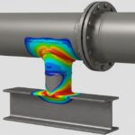
![3D CAD model of a pipe trunnion dummy support welded to a process pipeline resting on structural steel.]()
How to Perform Pipe Trunnion Stress Calculation for Piping Systems
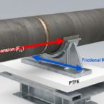
![3D CAD render of a sliding pipe support with PTFE slide plate and force vectors]()
How Pipe Support Friction Coefficient Affects Piping Stress Analysis
![Dual insulated piping system with specialized pipe support shoes in an industrial facility.]()
How to Master Supporting Dual Insulated Piping Systems Safely
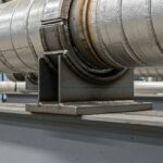
![Industrial pipe shoe welded to an insulated pipeline resting on a steel support beam.]()
What is a Pipe Shoe? Its Types and Functions Explained
![Industrial piping vibration isolator installed on a metal pipe in a mechanical room.]()
What Are Piping Vibration Isolators and How Do They Work
![A 3D render of an industrial Double Block and Bleed valve installed on a pipeline.]()
What is a Double Block and Bleed Valve and How Does It Work?