Table of Contents

What is Radiographic Testing? Its Types, Principles, Procedures, Standards, Advantages, and Disadvantages
In my 20 plus years of managing piping integrity on high-pressure oil and gas projects, I have seen many weld inspection methods come and go. Yet, radiographic testing remains the gold standard when you need an indisputable, permanent visual record of a weld’s internal health. Whether we are dealing with heavy-wall steam piping or critical offshore pipelines, understanding how to apply RT correctly can mean the difference between a safe, decades-long operating life and a catastrophic field failure.
On my project sites, I always tell junior engineers that radiographic testing is not just about taking an “X-ray” of a pipe. It is a highly regulated, physics-driven science that requires precise geometry, correct isotope selection, and strict adherence to safety protocols. If you do not understand the relationship between source-to-film distance, geometric unsharpness, and material density, you will end up with uninterpretable films and costly re-shoots.
Key Takeaways from an Expert’s Perspective
- Volumetric Accuracy: RT excels at identifying volumetric defects like slag inclusions, porosity, and gas pockets that surface-only methods miss.
- Permanent Record: Unlike ultrasonic testing, radiographic testing provides a physical or digital radiograph that can be archived and re-evaluated years later.
- Safety First: Managing radiation exclusion zones is a critical field responsibility that cannot be compromised.
- Code Compliance: Always cross-reference your film density and sensitivity against ASME Section V requirements.
How Does Radiographic Testing Inspect Welds?
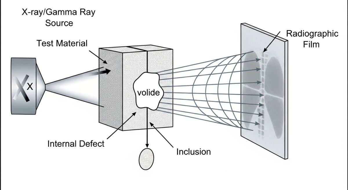
Radiographic Testing Principles: The differential absorption of ionizing radiation as it passes through a material to create a latent image on a detector or film. Thicker or denser areas absorb more radiation, while voids, cracks, or inclusions allow more radiation to pass through, revealing internal anomalies.
To truly master radiographic testing, we must look at the underlying physics. When high-energy photons (either X-rays or gamma rays) penetrate a metallic specimen, they interact with the material’s atomic structure. This interaction leads to attenuation, which is a combination of photoelectric absorption and Compton scattering.
The basic mathematical relationship governing this attenuation is expressed by the Beer-Lambert Law:
Where:
• I is the transmitted intensity of the radiation.
• I_0 is the initial incident intensity.
• mu is the linear attenuation coefficient of the material (which depends on the material density and radiation energy).
• x is the thickness of the material.
When a weld contains a defect, such as a gas pore or a crack, the local thickness (x) or density is reduced. Consequently, fewer photons are absorbed in that specific path, resulting in a higher intensity (I) reaching the radiographic film. On the developed film, this area appears darker (higher optical density), allowing a certified inspector to identify the exact shape and nature of the defect.
In my experience, ignoring geometric unsharpness (Ug) is the most common cause of rejected radiographs. ASME Section V Article 2 dictates strict limits on Ug. If your source-to-film distance is too short, or your source focal spot size is too large, the edges of your image will blur, masking critical cracks. Always calculate your minimum source-to-object distance using the formula: Ug = f * d / D.
Calculating Geometric Unsharpness (Ug)
Let us walk through a practical field calculation. Suppose we are inspecting a heavy-wall pipe weld with a nominal wall thickness of 32 mm using an Iridium-192 source. The source focal spot size (f) is 2.5 mm. The distance from the source to the weld surface (D) is 300 mm, and the distance from the weld surface to the film (d) is 32 mm.
Ug = (2.5 mm * 32 mm) / 300 mm
Ug = 80 / 300
Ug = 0.267 mm
According to ASME Section V Article 2, for material thicknesses under 50 mm, the maximum allowable geometric unsharpness is 0.51 mm. Since our calculated Ug of 0.267 mm is well below this limit, this setup is technically acceptable and will yield a sharp, compliant image.
Selecting Sources for Radiographic Testing Inspections
RT Source Selection: The process of matching the radiation energy level of X-ray machines or gamma isotopes to the material type and thickness. Proper selection ensures optimal radiographic sensitivity and contrast in compliance with ASTM E94.
Choosing the correct radiation source is a balance between penetration capability and image contrast. Low-energy sources provide excellent contrast but cannot penetrate thick steel. Conversely, high-energy sources like Cobalt-60 can penetrate massive castings but will burn through thin-walled piping, leaving a washed-out image with poor sensitivity.
| Radiation Source | Type | Energy Level / Voltage | Steel Thickness Range | Half-Life |
|---|---|---|---|---|
| X-Ray Tube (Low) | Electrical | 50 kV to 150 kV | Up to 10 mm | N/A (Instant Off) |
| X-Ray Tube (Medium) | Electrical | 150 kV to 450 kV | 10 mm to 50 mm | N/A (Instant Off) |
| Selenium-75 (Se-75) | Gamma Isotope | 0.26 MeV (Average) | 5 mm to 40 mm | 120 Days |
| Iridium-192 (Ir-192) | Gamma Isotope | 0.35 MeV (Average) | 12 mm to 75 mm | 74 Days |
| Cobalt-60 (Co-60) | Gamma Isotope | 1.25 MeV (Average) | 40 mm to 200 mm | 5.27 Years |
To ensure consistent quality across different testing agencies, we use standardized parameters. The table below maps the critical technical entities, their physical parameters, and the governing codes.
| Entity / Acronym | Technical Definition | Key Parameter / Limit | Reference Standard |
|---|---|---|---|
| IQI (Penetrameter) | Image Quality Indicator used to verify radiographic sensitivity and resolution. | Wire diameter or hole size must be visible on the film. | ASTM E1025 / ISO 19232 |
| H&D Density | The degree of film darkening measured using a calibrated densitometer. | 2.0 to 4.0 for X-ray; 1.8 to 4.0 for Gamma-ray. | ASME Sec V Art 2 |
| SFD | Source-to-Film Distance; controls geometric unsharpness and exposure time. | Calculated based on inverse square law for exposure. | ASTM E94 |
| RT Class | Classification of radiographic film based on grain size and speed. | Class I (Ultra-fine grain) to Class IV (Fast film). | ASTM E1815 |
Field Checklist for Radiographic Testing Safety
RT Field Verification: A systematic safety and quality protocol executed prior to exposing any radioactive source on an industrial job site. This checklist ensures compliance with OSHA radiation limits and ASME Section V quality requirements.
When you are managing a live construction site, safety is your absolute priority. Radioactive isotopes do not give you a second chance. I have developed this field checklist over two decades to ensure that every exposure is both safe and technically compliant.
Pre-Exposure Field Verification Steps
-
Radiation Work Permit (RWP): Verify that a valid, signed RWP is active for the specific shift and location.
-
Exclusion Zone Calculation: Calculate the safe boundary distance (typically 2 mR/hr limit) using a calibrated survey meter.
-
Barricades and Signage: Erect physical rope barriers with high-visibility “Caution: Radiation Area” signs and flashing red lights.
-
IQI Selection: Ensure the correct wire-type or hole-type Image Quality Indicator is placed on the source side of the weld.
-
Lead Letter Identification: Confirm that unique weld numbers, welder IDs, and date markers are placed on the specimen.
-
Emergency Retrieval Kit: Verify that a lead-lined emergency “pig” container and remote handling tongs are on-site in case of a source hang-up.
Field Case Study: Real-World Application
The Problem: High-Pressure Gas Pipeline Weld Failures
During the construction of a 24-inch, API 5L X65 high-pressure natural gas pipeline, the field team reported a series of micro-cracks and lack of root fusion in the girth welds. The initial ultrasonic testing (UT) results were ambiguous due to the coarse grain structure of the field welds, leading to disputes between the welding contractor and the quality control team.
The Solution: Transition to Panoramic Radiographic Testing
I stepped in and mandated a transition to panoramic radiographic testing using a Selenium-75 gamma source placed internally via a pipeline crawler. This setup allowed us to expose the entire 360-degree girth weld on a single film strip wrapped around the pipe’s exterior. We utilized Class I fine-grain film and wire-type IQIs to achieve maximum sensitivity.
The results were immediate and undeniable. The radiographs clearly revealed systematic lack of root fusion and fine copper inclusions caused by damaged welding torch tips. The high-contrast images provided the welding contractor with clear visual evidence of their technique errors, ending the dispute.
Frequently Asked Engineering Questions
What is the difference between X-ray and Gamma-ray testing?
How do you select the correct IQI (Penetrameter) size?
What are the main limitations of radiographic testing?
What is the acceptable optical density range for industrial film?
How does digital radiography differ from conventional film RT?
What is the purpose of lead screens in radiographic testing?
===
Complete Course on
Piping Engineering
Check Now
Key Features
- 125+ Hours Content
- 500+ Recorded Lectures
- 20+ Years Exp.
- Lifetime Access
Coverage
- Codes & Standards
- Layouts & Design
- Material Eng.
- Stress Analysis

📚 Recommended Resources: radiographic testing
Read these Guides
🎓 Advanced Training

Related posts:
![A mechanical sucker rod pumpjack operating in an oil field at sunset]()
What is Sucker Rod Pump System in Oil Production?
![Piping material engineer reviewing technical specifications on a tablet in an industrial plant.]()
How a Piping Material Engineer Drives Industrial Project Success
![Industrial refinery plant showing various types of static equipment]()
What is Static Equipment? Types and List of Static Equipments
![Side-by-side comparison of industrial process piping and power plant steam piping systems.]()
Differences Between ASME B31.3 and B31.1: B31.3 vs B31.1
![Large industrial steel storage tank under construction with cranes and scaffolding]()
Storage Tank Construction Method Statement: Step-by-Step Engineering Guide
![Cutaway diagram of a globe control valve highlighting the internal valve trim components]()
What is a Valve Trim? Types, Components, and Selection


