Selecting the Best Piping Supports in Oil and Gas
In my 20 years of designing piping systems for offshore platforms and onshore refineries, I have seen how a single poorly selected support can shut down an entire facility. I remember a project where a rigid shoe support was mistakenly installed instead of a variable spring hanger on a high-temperature steam line. Within three weeks, the thermal expansion forced the pipe upward, overloading a pump nozzle and causing a major hydrocarbon leak. That incident drove home a fundamental truth: piping supports are not passive steel brackets; they are dynamic structural elements that dictate the safety of the entire plant.
Selecting the correct support requires a deep understanding of thermal displacement, static weight distribution, and dynamic forces. In this guide, I will share my field-tested insights into classifying, designing, and installing these critical components to ensure your piping systems remain safe, compliant, and highly reliable.
Key Engineering Takeaways
- Rigid supports handle deadweight but restrict thermal growth.
- Spring hangers absorb vertical thermal displacement without overloading nozzles.
- Dynamic supports like snubbers protect against seismic and water hammer events.
- Proper spacing prevents sag and maintains slope for drainage.
- Material compatibility prevents galvanic corrosion at contact points.
Complete Course on
Piping Engineering
Check Now
Key Features
- 125+ Hours Content
- 500+ Recorded Lectures
- 20+ Years Exp.
- Lifetime Access
Coverage
- Codes & Standards
- Layouts & Design
- Material Eng.
- Stress Analysis
Designing Piping Supports in Oil and Gas
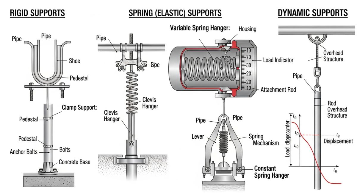
When designing piping systems, we classify supports into three primary functional categories: rigid, elastic (spring), and dynamic. Each category serves a specific purpose in managing the forces exerted by the piping system on surrounding structures and equipment.
1. Rigid Supports
Rigid supports prevent movement in specific directions without allowing any deflection. They are the most common supports used to carry deadweight loads.
- Anchors: Restrain all six degrees of freedom (three translational and three rotational). They are used to split piping systems into independent thermal expansion sections.
- Guides: Restrain lateral movement while allowing axial sliding. These are essential for preventing buckling in long pipe runs.
- Shoes: Metal attachments welded or clamped to the bottom of the pipe. They elevate insulated pipes above structural steel to prevent insulation damage and allow sliding.
2. Elastic (Spring) Supports
When a piping system undergoes significant vertical thermal expansion, rigid supports can cause massive thermal stresses or lift off completely. In these scenarios, we use spring supports.
- Variable Spring Hangers: The supporting force varies with the spring deflection. They are typically used when vertical movement is moderate (under 50 millimeters) and the load variation is acceptable.
- Constant Spring Hangers: These maintain a constant supporting force throughout the entire travel range. They are mandatory for critical piping connected to strain-sensitive equipment like steam turbines or compressors.
3. Dynamic Supports
Dynamic supports protect piping systems from sudden, transient loads such as water hammer, steam hammer, wind, and seismic events.
- Snubbers: Hydraulic or mechanical devices that allow slow thermal movement but lock up instantly during rapid dynamic events to restrain the pipe.
- Sway Braces: Spring-loaded devices that provide an opposing force to control steady-state vibration.
Thermal Expansion and Spring Rate Calculations
To calculate the thermal expansion of a carbon steel pipe, we use the linear expansion formula:
dL = L * alpha * dT
Where:
– dL is the total thermal expansion in millimeters.
– L is the length of the pipe run in meters.
– alpha is the mean coefficient of thermal expansion for the material (for carbon steel, this is approximately 0.012 millimeters per meter per degree Celsius).
– dT is the difference between the operating temperature and the ambient installation temperature in degrees Celsius.
For a 100-meter run of carbon steel pipe operating at 250 degrees Celsius with an installation temperature of 20 degrees Celsius, the expansion is:
dL = 100 * 0.012 * (250 – 20) = 276 millimeters.
Managing this 276 millimeters of movement requires a carefully engineered combination of expansion loops, guides, and spring hangers.
The spring rate (K) is determined by dividing the operating load (F) by the thermal travel (x):
K = F / x
According to ASME B31.3, the variability of a variable spring hanger must not exceed 25 percent. Variability is calculated as:
Variability = (Operating Load – Preset Load) / Operating Load * 100
If the variability exceeds 25 percent, a constant spring hanger must be specified instead to prevent excessive load transfer to adjacent equipment.
| Support Type | Typical Load Range (kN) | Temperature Limits (°C) | Primary Function | Standard Reference |
|---|---|---|---|---|
| Rigid Shoe | 5 to 500 | -29 to 400 | Elevate insulated pipe and allow axial sliding | MSS SP-58 |
| Variable Spring | 0.5 to 100 | -196 to 350 | Support vertical load with moderate thermal travel | ASME B31.3 |
| Constant Spring | 1 to 200 | -196 to 350 | Support vertical load with high thermal travel | ASME B31.3 |
| Hydraulic Snubber | 10 to 1000 | -20 to 120 | Restrain dynamic shock loads (seismic, water hammer) | ASME B31.3 |
| Rigid Anchor | 50 to 2000 | -29 to 600 | Restrain all six degrees of freedom | MSS SP-58 |
| Entity / Acronym | Technical Definition | Physical Parameter | Standard Reference |
|---|---|---|---|
| MSS SP-58 | Materials, design, manufacture, selection, application, and installation of pipe hangers and supports | Load capacity and temperature limits | MSS SP-58 Standard |
| ASME B31.3 | Code governing process piping design, materials, fabrication, assembly, erection, examination, inspection, and testing | Allowable stress and displacement limits | ASME B31.3 Code |
| Cold Load | The load exerted by the piping system on the spring support in its unheated, shut-down state | Force in Newtons or Kilonewtons | MSS SP-89 |
| Hot Load | The load exerted by the piping system on the spring support during normal operating conditions | Force in Newtons or Kilonewtons | MSS SP-89 |
| Travel Stop | A temporary metal pin or bar inserted into a spring hanger to lock the spring during hydrostatic testing | Displacement in millimeters | MSS SP-58 |
Installing Piping Supports in Oil and Gas
Proper installation is just as critical as correct design. If a support is installed incorrectly, the stress profile of the entire piping system changes, which can lead to catastrophic failures. Use this checklist during your next field walkdown to ensure compliance with MSS SP-89.
Pre-Commissioning Support Checklist
Field Case Study: Real-World Application
The Problem: Severe Vibration and Hanger Failure
During a commissioning phase at a natural gas processing plant in Western Canada, a 16-inch high-pressure gas line experienced severe, low-frequency vibration. The vibration was so intense that it caused visible movement in the supporting structural steel and led to the premature failure of two adjacent variable spring hangers. The plant was facing an unscheduled shutdown, costing upwards of 150,000 dollars per day in lost production. Our engineering team was called in to diagnose the root cause and implement an immediate solution.
The Outcome: Dynamic Mitigation and Redesign
We conducted a rapid piping stress analysis and field vibration survey. We discovered that the vibration was caused by acoustic resonance from an upstream reciprocating compressor. The existing variable spring hangers, while correctly sized for static thermal loads, lacked the damping capacity to handle the dynamic energy. We replaced the failed variable spring hangers with heavy-duty constant spring hangers to maintain constant load support, and we installed two hydraulic snubbers at critical node points. The snubbers allowed for slow thermal expansion during startup but locked up instantly during the high-frequency vibration cycles, effectively dampening the movement. The vibration amplitude was reduced by 85 percent, securing the structural integrity of the line and allowing the plant to resume full operations safely.
I highly recommend performing a dynamic modal analysis during the design phase for any piping system connected to reciprocating machinery. Relying solely on static stress analysis often leads to under-designed support systems that fail under real-world dynamic loads.
Frequently Asked Engineering Questions
What is the difference between a variable spring hanger and a constant spring hanger?
Why must travel stops be removed from spring hangers before plant startup?
How do you calculate the maximum spacing between piping supports?
What is the purpose of a pipe shoe, and when should it be used?
How do hydraulic snubbers differ from mechanical snubbers in dynamic piping systems?
What materials are recommended for piping supports in highly corrosive offshore environments?