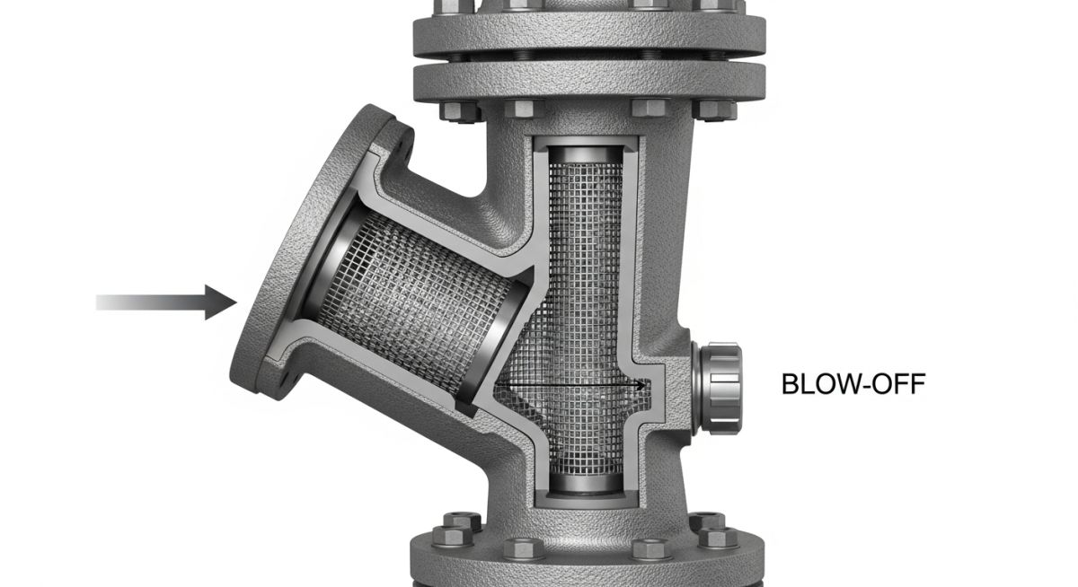
Piping Strainers: Applications, Types, and Design Standards
In my two decades of experience, I have seen countless pump failures and control valve malfunctions caused by simple, avoidable debris. Piping strainers are the unsung heroes of process plants, acting as the primary defense mechanism against solid contaminants. Whether you are dealing with high-velocity steam or viscous chemical slurries, the correct selection of a strainer is not just a maintenance choice; it is a fundamental requirement for system integrity.
This guide breaks down the technical nuances of strainer selection, from understanding the pressure drop across a screen to navigating the complexities of ASME B16.34 pressure-temperature ratings. We will move beyond basic catalog specs to look at real-world installation challenges.
Key Takeaways
- Understand the critical relationship between mesh size and differential pressure.
- Master the application of ASME standards for pressure-containing components.
- Learn to identify the specific failure modes associated with improper strainer orientation.
- Gain insights into material compatibility for corrosive and high-temperature services.
Piping Strainer Design Standards and Calculations
Piping Strainer Design Standards: The engineering framework governing the structural integrity, pressure containment, and material selection of strainers in accordance with ASME and API codes.
When designing a piping system, the strainer is treated as a pressure-containing component. I always reference ASME B16.34 for pressure-temperature ratings, ensuring the body material and wall thickness meet the piping class requirements. The most critical calculation in my workflow is the pressure drop across the strainer, which is governed by the Darcy-Weisbach equation modified for screen geometry.
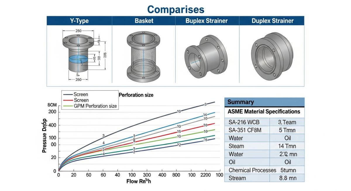
Calculating Pressure Drop
The total pressure drop is the sum of the body loss and the screen loss. The body loss is calculated using the standard valve flow coefficient (Cv), while the screen loss is a function of the open area ratio (OAR). I typically aim for an OAR of at least 3:1 to 4:1 to minimize maintenance frequency.
Field Warning: The Clogging Factor
Never ignore the “clogging factor” in your calculations. As the screen accumulates debris, the effective open area decreases, leading to an exponential increase in differential pressure. If your system design does not account for a 50% reduction in open area, you risk structural failure of the screen or, worse, a complete flow blockage that could trigger a pump cavitation event.
For high-pressure applications, I specify reinforced screens. A standard perforated plate might suffice for low-pressure water, but for high-velocity steam or hydrocarbon services, a mesh-lined perforated screen is mandatory to prevent screen collapse. Always verify the maximum allowable differential pressure (MADP) provided by the manufacturer against your system’s pump head curve.
Material Selection and Corrosion
Material selection must align with the piping specification. For carbon steel piping, I typically use ASTM A216 WCB bodies. However, in sour gas or corrosive chemical environments, I shift to stainless steel (ASTM A351 CF8M) or even exotic alloys like Monel or Hastelloy. The screen material is equally important; it must be galvanically compatible with the body to prevent accelerated corrosion at the contact points.
Strainer Performance Trade-offs: The technical balance between filtration efficiency, system pressure loss, and maintenance accessibility in industrial piping configurations.
Advantages
- Protects expensive downstream equipment like pumps and control valves.
- Reduces unplanned downtime by capturing debris before it causes damage.
- Available in various configurations to suit specific space constraints.
- Simple design allows for rapid inspection and screen cleaning.
- Cost-effective solution compared to the price of replacing damaged instrumentation.
Disadvantages
- Introduces a permanent pressure drop into the piping system.
- Requires regular maintenance and manual cleaning of the screen.
- Improper installation can lead to flow turbulence and vibration.
- Large basket strainers require significant footprint for removal.
- Risk of screen collapse if differential pressure limits are exceeded.
Industrial Filtration Deployment: The strategic integration of strainers into diverse process environments to ensure fluid purity and equipment longevity.
Steam Turbine Protection
In power generation, Y-strainers are installed upstream of steam turbines to capture pipe scale and welding slag. This prevents high-velocity erosion of turbine blades, which is a common cause of catastrophic failure in high-pressure steam systems.
Chemical Feedstock Processing
Basket strainers are utilized in chemical plants to filter raw feedstocks before they enter sensitive reactors. By removing particulate matter, these strainers prevent catalyst poisoning and ensure consistent reaction kinetics across the production cycle.
Cooling Water Systems
Large-scale cooling water loops rely on duplex strainers to allow for continuous operation. Because the system cannot be shut down for cleaning, the duplex design enables the operator to switch flow to a clean basket while the other is serviced.
Hydrocarbon Pipeline Integrity
In midstream oil and gas, temporary strainers are often used during commissioning to catch construction debris. Once the line is flushed, these are replaced with permanent, high-capacity strainers to protect downstream metering stations and pumps.
Selecting the correct strainer requires a rigorous evaluation of the fluid properties, operating pressure, and the specific particle size distribution expected within the process stream. In my experience, engineers often overlook the relationship between the open area ratio and the resulting pressure drop, which can lead to premature pump cavitation or system-wide flow instability.
The following table outlines the critical performance metrics for standard industrial strainer configurations. These values are based on clean water at ambient temperatures; for high-viscosity fluids or non-Newtonian slurries, you must apply a correction factor to the Cv values provided by the manufacturer to ensure the system remains within the allowable pressure drop limits defined by ASME B31.3.
| Strainer Type | Typical Mesh/Perf | Pressure Drop Factor | Maintenance Frequency |
|---|---|---|---|
| Y-Strainer | 20-400 Mesh | High (1.5 – 2.5) | Frequent |
| Basket Strainer | 0.5mm – 5mm | Low (0.5 – 1.2) | Moderate |
| Duplex Strainer | Custom | Low (0.8 – 1.5) | Continuous |
Always verify that the selected strainer body material matches the piping specification class. Using a carbon steel strainer in a stainless steel process line will introduce galvanic corrosion risks, potentially compromising the integrity of the pressure boundary over time.
The following matrix maps the essential technical entities required for the procurement and installation of industrial strainers. Understanding these parameters is vital for ensuring that the equipment meets the stringent requirements of modern process plants, particularly where high-pressure or hazardous fluids are involved.
Each entity listed below corresponds to a specific design constraint or regulatory standard. By aligning these variables during the FEED (Front-End Engineering Design) phase, you can prevent costly field modifications and ensure that the filtration system provides the necessary protection for downstream rotating equipment like pumps, compressors, and control valves.
| Entity | Standard Reference | Primary Function |
|---|---|---|
| Pressure Boundary | ASME B16.34 | Structural Integrity |
| Flange Dimensions | ASME B16.5 | Mechanical Connection |
| Filtration Media | ASTM E11 | Particle Retention |
This matrix serves as a baseline for technical audits. Ensure that all vendor documentation explicitly references these standards to maintain compliance with site-specific safety protocols and quality assurance programs.
Proper installation is the final gatekeeper for system reliability. Before commissioning any strainer, I mandate a thorough site verification process to ensure that the orientation, accessibility, and support structures are correctly implemented according to the piping isometric drawings and vendor manuals.
- 1. Verify flow direction arrow on the strainer body matches the process flow direction.
- 2. Ensure adequate clearance for basket removal (minimum 1.5 times the basket length).
- 3. Confirm that the drain valve is installed at the lowest point of the strainer housing.
- 4. Check that the pressure gauges are installed upstream and downstream to monitor differential pressure.
- 5. Validate that the support structure prevents pipe stress from being transferred to the strainer body.
- 6. Inspect the gasket material compatibility with the process fluid and operating temperature.
During the pre-commissioning walkdown, pay close attention to the differential pressure monitoring setup. If the gauges are not calibrated or if the isolation valves are not properly tagged, the operators will be unable to determine when the basket requires cleaning. This oversight is a leading cause of pump failure in high-debris environments. Always ensure that the strainer is isolated and depressurized before attempting any maintenance, following strict Lock-Out Tag-Out (LOTO) procedures. If the strainer is installed in a vertical line, confirm that the flow is downward to prevent debris from falling back into the piping system during maintenance activities.
Problem: Premature Pump Cavitation in Cooling Water Loop
- The Y-strainer was installed horizontally in a high-velocity cooling water line.
- Debris accumulation caused a pressure drop exceeding the pump’s Net Positive Suction Head (NPSH) margin.
- The lack of a differential pressure gauge prevented early detection of the clogged screen.
- Vibration from the pump caused the strainer gasket to fail, leading to a significant process leak.
Outcome: System Optimization and Reliability Improvement
- Replaced the Y-strainer with a basket strainer to increase the open area ratio.
- Installed a differential pressure transmitter with a local alarm to alert operators.
- Implemented a scheduled maintenance program based on pressure drop trends rather than time intervals.
- Added a permanent support cradle to isolate the strainer from piping thermal expansion forces.
My recommendation for similar systems is to prioritize the use of basket strainers over Y-strainers in high-flow applications. The increased surface area of the basket significantly reduces the frequency of maintenance and minimizes the risk of sudden pressure drops that can lead to catastrophic pump failure.
What is the primary difference between Y-strainers and basket strainers?
How do I calculate the pressure drop across a strainer?
- Determine the maximum flow rate for the process.
- Obtain the clean Cv value from the manufacturer’s data sheet.
- Apply a correction factor if the fluid viscosity is significantly higher than water.
- Ensure the calculated pressure drop does not exceed the system’s allowable limit at the maximum expected debris loading.
When should I specify a duplex strainer?
- Use in critical cooling water loops or fuel supply lines.
- Ideal for processes where downtime results in significant financial loss.
- Allows for the cleaning of one basket while the other remains in service.
- Requires careful operation of the switching valve to prevent pressure surges.
What materials are best for corrosive process fluids?
- Consult the project’s Material Selection Diagram (MSD).
- Ensure the screen material matches the housing to prevent galvanic corrosion.
- Verify that the gasket material is compatible with the chemical concentration and temperature.
How does ASME B16.34 apply to strainer design?
What is the importance of the open area ratio?
- A ratio of 3:1 or higher is generally recommended for most industrial applications.
- Lower ratios lead to rapid pressure drops as debris accumulates.
- Always check the manufacturer’s data to ensure the ratio is sufficient for your specific fluid velocity and particle loading.
📚 Recommended Resources: Piping Strainers
Read these Guides
🎓 Advanced Training


Complete Course on
Piping Engineering
Check Now
Key Features
- 125+ Hours Content
- 500+ Recorded Lectures
- 20+ Years Exp.
- Lifetime Access
Coverage
- Codes & Standards
- Layouts & Design
- Material Eng.
- Stress Analysis
