How to Review and Select Piping Specialty Items Safely
In my 20-plus years of piping engineering, I have seen many projects run smoothly on standard fittings only to grind to a sudden halt because of a single poorly specified specialty item. I remember a project in 2014 where a temporary cone strainer collapsed inside a compressor suction line during commissioning. The debris shredded the first-stage impellers, costing the client three million dollars in repairs and months of delay. That disaster could have been avoided with a simple, rigorous engineering review of the strainer’s structural collapse pressure.
Piping specialty items (often called SP items) are the unsung heroes and potential single points of failure in industrial plants. Because they do not fit neatly into standard ASME B16.5 or B16.9 dimensions, they require a dedicated review process. We must evaluate their pressure-containing capability, material compatibility, and structural interaction with the surrounding piping system.
Key Engineering Takeaways
- Understand the difference between standard piping components and specialty items (SP items).
- Master the ASME B31.3 Paragraph 304.7.2 validation methods for unlisted components.
- Learn how to calculate strainer open area ratios and equivalent pressure loads.
- Establish a robust field verification checklist to prevent installation errors.
Why Do Piping Specialty Items Require Custom Engineering?
When we design a piping system using standard elbows, tees, and flanges, we rely on the pressure-temperature ratings established by standards like ASME B16.5. However, for piping specialty items such as basket strainers, expansion joints, and sight glasses, no such universal standard exists. These are classified as “unlisted components” under ASME B31.3.
According to ASME B31.3 Paragraph 304.7.2, the pressure design of unlisted components must be verified using one of five strict methods:
- Extensive successful service experience under comparable operating conditions.
- Experimental stress analysis in accordance with ASME Section VIII, Division 2, Annex 5-F.
- Analytical calculations (such as Finite Element Analysis – FEA) per ASME Section VIII, Division 2, Part 5.
- Proof testing in accordance with ASME B16.9, MSS SP-97, or ASME Section VIII, Division 1, UG-101.
- Detailed calculations using recognized engineering standards.
Strainer Open Area Ratio (OAR) Calculation
One of the most common reviews I perform is for basket and Y-strainers. If the open area of the strainer basket is too small, the pressure drop across the strainer will be excessive, leading to cavitation, flow restriction, or element collapse. The Open Area Ratio (OAR) is calculated as follows:
Let us walk through a real-world design example. Suppose we have an 8-inch Schedule 40 pipe basket strainer.
- • Nominal pipe size = 8 inches
- • Inside diameter of 8-inch Schedule 40 pipe = 7.981 inches
- • Internal cross-sectional area of the pipe (A_pipe) = (3.1416 * 7.981^2) / 4 = 50.02 square inches
- • Strainer basket dimensions: Diameter = 9.5 inches, Length = 18 inches
- • Basket surface area (cylinder + flat bottom): A_basket = (3.1416 * 9.5 * 18) + ((3.1416 * 9.5^2) / 4) = 537.21 + 70.88 = 608.09 square inches
- • Perforated plate open area = 50% (0.50)
- • Mesh screen open area = 38% (0.38)
Now, we calculate the total open area of the basket (A_open):
Finally, we calculate the Open Area Ratio (OAR):
In my experience, for a basket strainer in liquid service, we look for an OAR of at least 4:1. A ratio of 2.31:1 is too low and will cause rapid blinding and high clean pressure drops. I would reject this design and request a larger strainer body (e.g., a 10-inch or 12-inch body with 8-inch nozzles) to achieve an OAR of 4:1 or higher.
Equivalent Pressure on Specialty Flanged Joints
Piping specialty items are often heavy and introduce external bending moments and axial forces onto adjacent flanges. To ensure these joints do not leak, we must calculate the equivalent pressure (P_eq) using the Kellogg method:
Where:
- • P_design = Internal design pressure (psi)
- • M = External bending moment (in-lb)
- • F = External axial force (lb)
- • G = Gasket reaction diameter (inches)
If the calculated P_eq exceeds the maximum allowable pressure rating of the flange at the design temperature per ASME B16.5, the joint is unsafe, and we must modify the piping support scheme to reduce the external loads.
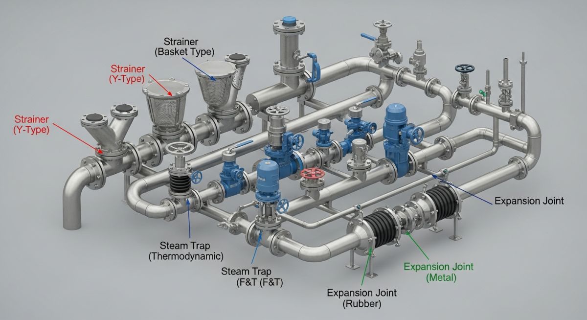
To streamline the engineering review process, I have compiled a reference table of common piping specialty items, their primary design codes, and the key parameters that you must verify during the design phase.
| Specialty Item | Primary Function | Applicable Codes | Key Review Parameters |
|---|---|---|---|
| Y-Strainer / Basket Strainer | Removes solid particles from process fluid | ASME B31.3, MSS SP-115 | Open area ratio, mesh size, pressure drop, body wall thickness |
| Metallic Bellows Expansion Joint | Absorbs thermal expansion and vibration | ASME B31.3 App. X, EJMA Standards | Spring rate, cycle life, squirm pressure, shipping bar removal |
| Flame Arrestor | Prevents flame propagation in piping | API RP 2028, ISO 16852 | Explosion group, maximum experimental safe gap (MESG), pressure drop |
| Steam Trap | Discharges condensate without losing steam | ASME B31.3, FCI 69-1 | Discharge capacity, body rating, subcooling temperature |
| Sight Flow Indicator | Visual verification of fluid flow | ASME B31.3, ASME Section VIII | Glass thermal shock rating, shield protection, body material |
| Entity / Acronym | Technical Definition | Physical Parameter / Unit | Reference Standard |
|---|---|---|---|
| OAR | Ratio of strainer open area to pipe area | Dimensionless (e.g., 4:1) | ASME B31.3 |
| EJMA | Expansion Joint Manufacturers Association | N/A | EJMA Standards |
| MESG | Maximum Experimental Safe Gap | Millimeters (mm) | ISO 16852 / API RP 2028 |
| Cv | Flow Coefficient | gpm/psi^0.5 | ISA 75.01 |
| Squirm Pressure | Pressure at which bellows undergoes buckling | psi / bar | ASME B31.3 Appendix X |
How to Verify Piping Specialty Items on Site
Before any piping system is pressurized or handed over to operations, a physical walkdown of all piping specialty items is mandatory. In my experience, construction crews often treat these items like standard fittings, which leads to critical installation errors. Use the checklist below during your next field walkdown.
Field Walkdown Checklist
-
Flow Direction Arrow: Verify that the physical flow direction arrow cast or stamped on the component body matches the actual process flow direction shown on the piping isometric drawing.
-
Pressure Rating Verification: Confirm that the pressure rating on the manufacturer nameplate matches or exceeds the piping class specification (e.g., Class 300, Class 600) and is not limited by internal elements like glass or gaskets.
-
Bellows Shipping Bars: Check that temporary shipping bars on bellows expansion joints are painted a bright, contrasting color (usually yellow or red) and remain intact until after successful hydrotesting.
-
Steam Trap Orientation: Ensure steam traps are installed in the correct horizontal or vertical orientation as specified by the manufacturer to prevent condensate backup or steam loss.
-
Strainer Mesh Inspection: Verify that the strainer mesh size and material match the piping specialty datasheet, and that the mesh is clean and free of construction debris.
-
Sight Glass Integrity: Inspect sight glass indicators for any scratches, chips, or cracks before system pressurization, and verify that protective shields are installed.
Field Case Study: Real-World Application
The Case of the Buckled Bellows
During commissioning of a high-temperature steam line (450°C, 45 barg) at a petrochemical plant, a metallic bellows expansion joint failed catastrophically during the initial heat-up cycle. The bellows suffered severe lateral deformation (squirm) and ruptured, releasing high-pressure steam and forcing an emergency shutdown.
Our investigation revealed two critical engineering oversights. First, the piping stress analysis had modeled the bellows as a rigid anchor rather than inputting the actual lateral and axial spring rates from the manufacturer’s datasheet. Second, the field construction crew had failed to install the main piping guides on either side of the expansion joint, leaving the pipe free to buckle under the pressure thrust force.
Engineering Remediation and System Stabilization
I led the recovery team to redesign the piping system. We updated the stress model in CAESAR II using the exact EJMA-compliant spring rates: axial spring rate of 450 lb/in and lateral spring rate of 1,200 lb/in. We added robust main anchors and pipe guides at 4D and 14D distances from the bellows as specified by EJMA standards to control the pressure thrust force of 18,500 lb.
A new bellows was installed, shipping bars were removed only after a successful hydrotest at 67.5 barg, and the system was heated up safely. The piping system has now operated for over five years without a single millimeter of unexpected movement or vibration.
My direct recommendation is to always verify that piping guides are installed exactly per EJMA guidelines and that bellows spring rates are explicitly modeled in your stress analysis software. Never treat an expansion joint as a simple piece of pipe.
How to Manage Piping Specialty Items in Stress Analysis
What is the difference between a piping specialty item and a standard piping component?
How do you calculate the pressure thrust force in a bellows expansion joint?
Why must shipping bars be removed from expansion joints, and when should this occur?
What is the minimum open area ratio (OAR) for a permanent basket strainer?
How do you validate an unlisted piping specialty item under ASME B31.3?
What are the key design considerations for installing a flame arrestor?
Complete Course on
Piping Engineering
Check Now
Key Features
- 125+ Hours Content
- 500+ Recorded Lectures
- 20+ Years Exp.
- Lifetime Access
Coverage
- Codes & Standards
- Layouts & Design
- Material Eng.
- Stress Analysis

📚 Recommended Resources: Piping Specialty Items
Read these Guides
🎓 Advanced Training


Related posts:
![3D engineering visualization of a piping system undergoing thermal expansion with stress concentration points highlighted in red and yellow.]()
Piping Flexibility Analysis: Essential Requirements for Safe Industrial Design
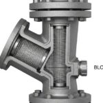
![Industrial Y-type piping strainer installed in a high-pressure steel pipeline with visible flanged connections and blow-off valve.]()
Piping Strainers: Design Standards, Selection Criteria, and Industrial Applications
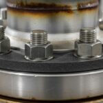
![Industrial flange connection with high-strength alloy steel studs and nuts in a refinery piping system.]()
How to Select a Bolt: The Complete Engineering Selection Process
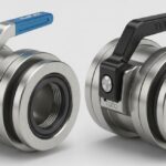
![Close-up view of industrial Elaflex and Todo hose couplings showing locking mechanisms and stainless steel construction for chemical transfer.]()
Industrial Hose Couplings: Elaflex and Todo Coupling Design Guide
![3D isometric plot plan showing the strategic placement of reactors, fired heaters, and pressure vessels in a refinery.]()
Strategic Location of Static Equipment: Fired Heaters, Reactors, and Drums
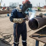
![Professional welder performing high-precision field welding on industrial piping in a refinery construction site.]()
General Requirements for Field Welding: A Piping Engineering Guide