Table of Contents
How Pipe Support Friction Coefficient Affects Piping Stress Analysis
In my 20 years of piping engineering experience, I have seen many pipe stress engineers treat the pipe support friction coefficient as a minor detail. They plug a default value of 0.3 into their stress analysis software and move on. This is a dangerous mistake. Frictional loads on pipe supports can make or break a piping system, especially when dealing with high-temperature lines, sensitive equipment connections, or lightweight structural steel. When a pipe expands thermally, it slides across its supports. The resistance to this movement creates a force that is transmitted directly back into the piping system and the supporting structure.
If you underestimate this coefficient, you risk buckling structural steel, overloading sensitive pump or turbine nozzles, and causing premature support failure. Conversely, overestimating it can lead to overly conservative, expensive structural designs and unnecessary expansion loops. Let us dive deep into how to select, calculate, and verify these values to ensure your piping systems remain safe and cost-effective.
Key Engineering Takeaways
- Understand how sliding friction directly impacts structural steel design and equipment nozzle loading.
- Learn the realistic friction values for steel-on-steel, PTFE, graphite, and bronze sliding interfaces.
- Discover how to model friction accurately in piping stress analysis software like CAESAR II.
- Identify the field conditions that can double your design friction coefficients over time.
- Implement a robust site verification protocol to ensure field installations match design assumptions.
Complete Course on
Piping Engineering
Check Now
Key Features
- 125+ Hours Content
- 500+ Recorded Lectures
- 20+ Years Exp.
- Lifetime Access
Coverage
- Codes & Standards
- Layouts & Design
- Material Eng.
- Stress Analysis
Understanding Pipe Support Friction Coefficient in Design
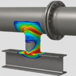
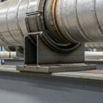
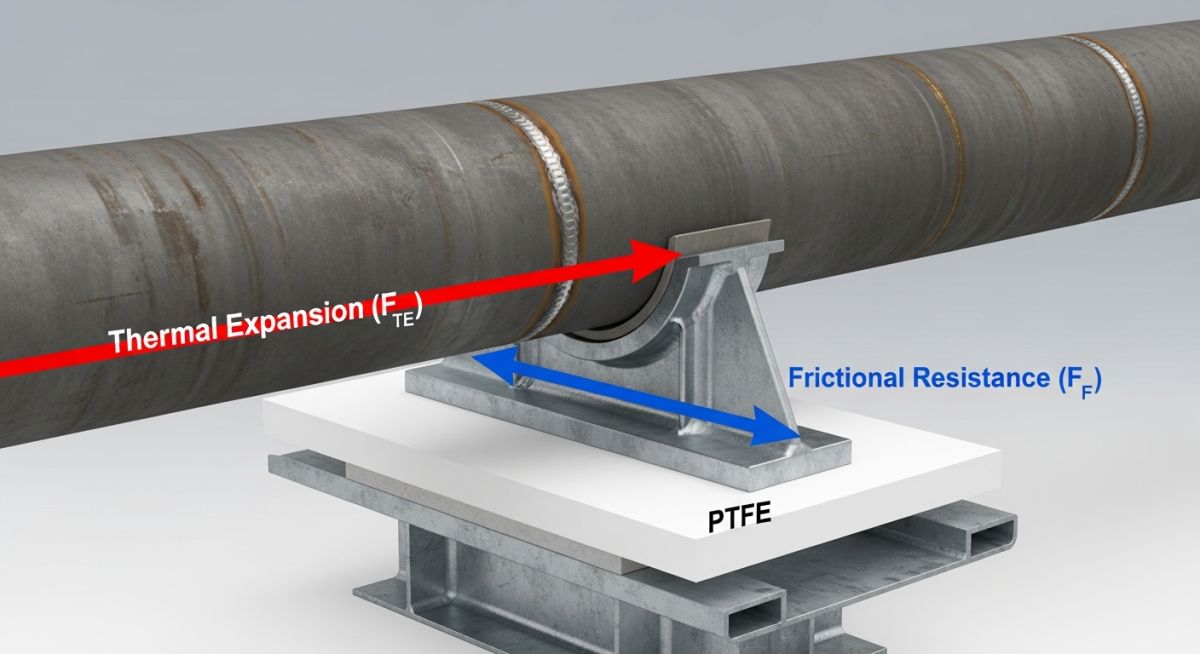
To understand the impact of friction, we must look at the basic physics of sliding interfaces. When a pipe shoe rests on a structural steel beam, the weight of the pipe and its contents creates a normal force. As the pipe undergoes thermal expansion, it attempts to move axially or laterally. The resistance to this movement is governed by Coulomb’s law of dry friction.
The friction force is calculated using the following formula:
Where the normal force is the vertical operating load on the support, and the friction coefficient is determined by the materials in contact. In piping stress analysis, this friction force acts as a concentrated load in the direction opposite to the pipe’s thermal movement. This force must be resisted by the pipe shoe, the structural steel frame, and the pipe wall itself.
Under ASME B31.3 Process Piping, engineers must account for all sustained, occasional, and displacement (thermal) loads. Frictional loads fall under displacement loads because they are driven by thermal expansion. However, they behave like sustained loads on the structural steel. If a pipe shoe binds or experiences high friction, it can transfer massive forces to the structural steel, leading to structural yielding or buckling.
Modeling Friction in Piping Stress Analysis
When performing piping stress analysis in software like CAESAR II, you must define the friction coefficient (Mu) for every sliding support. The software uses this value to perform non-linear iterations. Because friction is a path-dependent, non-linear force, the software must determine whether the thermal force is large enough to overcome static friction. If the thermal force is less than the static friction force, the pipe will not slide, and the support will act as a rigid anchor in that direction.
This non-linear behavior can lead to unexpected stress distributions. For example, if a pipe is held in place by friction at several intermediate supports, the thermal expansion will accumulate and dump a massive load on the nearest rigid anchor or equipment nozzle. This is why selecting the correct friction coefficient is so critical for accurate stress modeling.
Standard Pipe Support Friction Coefficient Values
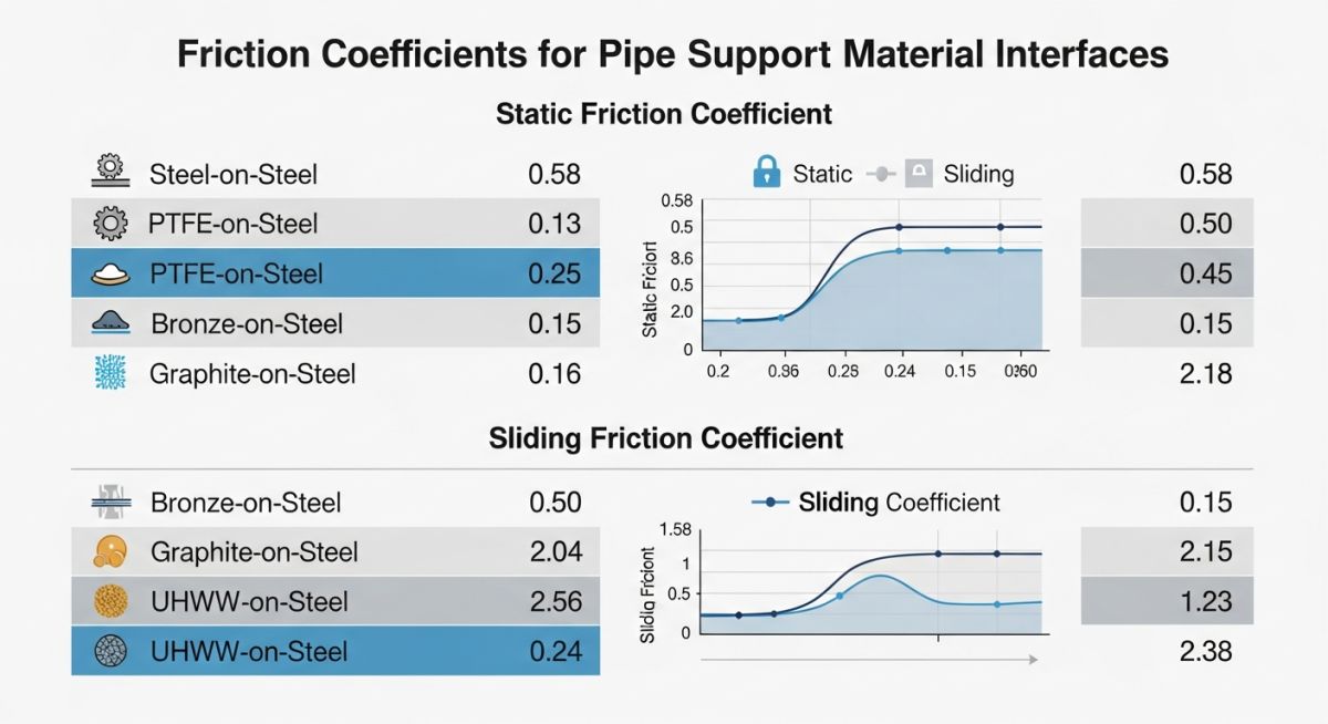
The table below outlines the standard friction coefficients used in the piping industry. These values are based on laboratory testing and field performance data. They represent a balance between realistic operating conditions and conservative design margins.
| Sliding Interface Materials | Clean/Dry Lab Value | Aged/Dirty Field Value | Recommended Design Value | Typical Application |
|---|---|---|---|---|
| Steel on Steel | 0.30 | 0.45 – 0.60 | 0.40 | Standard carbon steel pipe shoes on structural steel beams. |
| PTFE on Stainless Steel | 0.05 | 0.10 – 0.15 | 0.10 | Low-friction slide plates for heavy loads or sensitive nozzles. |
| Graphite on Steel | 0.15 | 0.20 – 0.25 | 0.20 | High-temperature applications where PTFE would degrade. |
| Bronze on Steel | 0.20 | 0.25 – 0.30 | 0.25 | Heavy-duty industrial sliding supports with moderate temperatures. |
This matrix maps the core technical entities, structural acronyms, physical parameters, and hyperlinked standard references associated with pipe support friction analysis.
| Technical Entity | Acronym / Symbol | Physical Parameter | Governing Standard |
|---|---|---|---|
| Coefficient of Friction | Mu (μ) | Dimensionless Ratio | AISC Steel Construction Manual |
| Polytetrafluoroethylene | PTFE | Polymer Slide Plate | ASTM D4894 |
| Frictional Load | F_f | Force (kN or lbs) | ASME B31.3 Clause 319.4.4 |
| Normal Operating Load | F_n | Force (kN or lbs) | ASME B31.1 Power Piping |
Verifying Pipe Support Friction Coefficient on Site
During construction and commissioning, field deviations can easily compromise your design assumptions. A single misplaced weld or a dirty slide plate can turn a low-friction PTFE support into a high-friction anchor. Use this checklist on-site to verify that your sliding supports are installed correctly and will perform as modeled.
Field Inspection Checkpoints
-
Verify Slide Plate Material: Confirm that the installed slide plate matches the design drawing (e.g., virgin PTFE, glass-filled PTFE, or graphite). Check material test reports (MTRs) for compliance.
-
Inspect Surface Finish: Ensure the mating stainless steel plate has a mirror finish (typically 2B or better). Scratches, weld splatter, or paint on the stainless steel plate will dramatically increase friction.
-
Check Alignment and Travel: Verify that the pipe shoe is centered on the slide plate at ambient temperature. Ensure the slide plate is wide and long enough to accommodate the full thermal travel calculated in the stress report.
-
Confirm Cleanliness: Ensure all construction debris, sand, and protective plastic coatings are completely removed from the sliding interface before the system is heated up.
-
Verify Parallelism: Check that the pipe shoe base and the structural steel bearing surface are perfectly parallel. Angular misalignment concentrates the load on one edge, crushing the PTFE and increasing friction.
Field Case Study: Real-World Application
The Problem: Buckling Structural Steel and Overloaded Turbine Nozzle
During the commissioning of a 12-inch high-pressure steam line operating at 350 degrees Celsius, field operators noticed visible bowing in a major structural steel support column. At the same time, the steam turbine manufacturer reported that the forces on the inlet nozzle exceeded the allowable limits defined by API 611.
The original piping stress analysis had assumed a standard steel-on-steel friction coefficient of 0.3 for all sliding shoes. However, due to heavy atmospheric corrosion in the coastal facility, the sliding surfaces had rusted significantly before startup. Field measurements indicated the actual friction coefficient had spiked to approximately 0.55, preventing the pipe from sliding smoothly and turning several sliding supports into unintended semi-anchors.
The Outcome: Retrofitting with PTFE Slide Plates
To resolve the issue without rerouting the piping or adding expensive expansion loops, I recommended retrofitting the critical sliding supports with PTFE-on-stainless steel slide plates. This modification dropped the design friction coefficient from 0.3 (and the actual 0.55) down to a reliable 0.10.
The results were immediate:
- The lateral frictional load on the bowing structural column dropped by over 70%, allowing the steel to return to its elastic state.
- The bending moments on the steam turbine inlet nozzle were reduced to 45% of the API 611 allowable limits, ensuring safe operation.
- The total cost of the retrofit was less than 15,000 USD, saving the project from a potential 250,000 USD structural redesign and weeks of schedule delays.
This case highlights the importance of looking beyond default software values. When dealing with high-temperature lines or sensitive equipment, investing in low-friction slide plates is a highly cost-effective way to manage thermal expansion forces.
Frequently Asked Engineering Questions
What is the standard pipe support friction coefficient for steel-on-steel?
When should I use PTFE slide plates instead of steel-on-steel?
How does temperature affect the friction coefficient of PTFE?
Should I model friction in both axial and lateral directions?
What is the difference between static and dynamic friction in piping?
Can I lubricate steel-on-steel supports to reduce friction?
===FAQ_BLOCK===

📚 Recommended Resources: pipe support friction coefficient
Related posts:
![3D CAD model of a pipe trunnion dummy support welded to a process pipeline resting on structural steel.]()
How to Perform Pipe Trunnion Stress Calculation for Piping Systems
![Dual insulated piping system with specialized pipe support shoes in an industrial facility.]()
How to Master Supporting Dual Insulated Piping Systems Safely
![Industrial pipe shoe welded to an insulated pipeline resting on a steel support beam.]()
What is a Pipe Shoe? Its Types and Functions Explained
![Industrial piping vibration isolator installed on a metal pipe in a mechanical room.]()
What Are Piping Vibration Isolators and How Do They Work
![A 3D render of an industrial Double Block and Bleed valve installed on a pipeline.]()
What is a Double Block and Bleed Valve and How Does It Work?
![A collection of different types of metal pipe clamps used in plumbing and industrial piping systems.]()
Various Types of Pipe Clamps for Piping and Plumbing Industry