Is Your Pipe Stress Range Calculation Actually Compliant?
Over my 20 years in piping engineering, I have reviewed hundreds of stress analysis reports. One of the most common errors I encounter is the misapplication of the displacement stress range. Many engineers treat thermal expansion as a static, one-time load rather than a cyclic fatigue phenomenon. This misunderstanding leads to catastrophic piping failures at elbows and nozzle connections.
When I audit a stress model, I do not just look at the final compliance flags. I dig deep into how the load cases are structured. If your software setup does not accurately reflect the physical transition from the cold shutdown state to the hot operating state, your calculations are built on sand. Let us break down how to verify these calculations to ensure your designs are safe, robust, and fully compliant with international codes.
Key Takeaways for Piping Engineers
- Understand the fundamental difference between sustained stresses and displacement stress ranges.
- Learn how to correctly apply the fatigue reduction factor based on total expected thermal cycles.
- Discover how to leverage the liberal stress range equation to optimize piping layouts without adding unnecessary expansion loops.
- Identify common software modeling pitfalls that lead to incorrect stress range outputs.
Why Pipe Stress Range Calculation Errors Happen
In my experience, the root cause of calculation errors is the confusion between primary and secondary stresses. Primary stresses, such as those from internal pressure and gravity, are non-self-limiting. If they exceed the yield strength of the material, the pipe will undergo continuous plastic deformation until it ruptures.
Secondary stresses, which drive the displacement stress range, are self-limiting. When a pipe heats up, it expands. If this expansion is restricted by anchors or supports, the pipe experiences thermal strain. Once the pipe yields locally, the strain is accommodated, and the stress relaxes. Therefore, the hazard here is not immediate burst failure, but rather progressive fatigue cracking over repeated thermal cycles.
FIELD WARNING: The Danger of Ignoring Transient States
Never rely solely on the difference between the ambient state and the design temperature. I once investigated a refinery piping failure where the system experienced intermediate steam-out conditions that were significantly hotter than the normal design temperature. Because the analyst omitted this transient state from the stress range evaluation, the actual displacement range was underestimated by 35%, leading to a fatigue crack at a branch connection within six months of operation.
To calculate the displacement stress range (S_E) accurately, we must use the formula defined in ASME B31.3 Paragraph 319.4.4:
Where:
• S_b is the resultant bending stress, incorporating stress intensification factors (SIFs).
• S_t is the torsional stress.
Mastering Pipe Stress Range Calculation Code Compliance
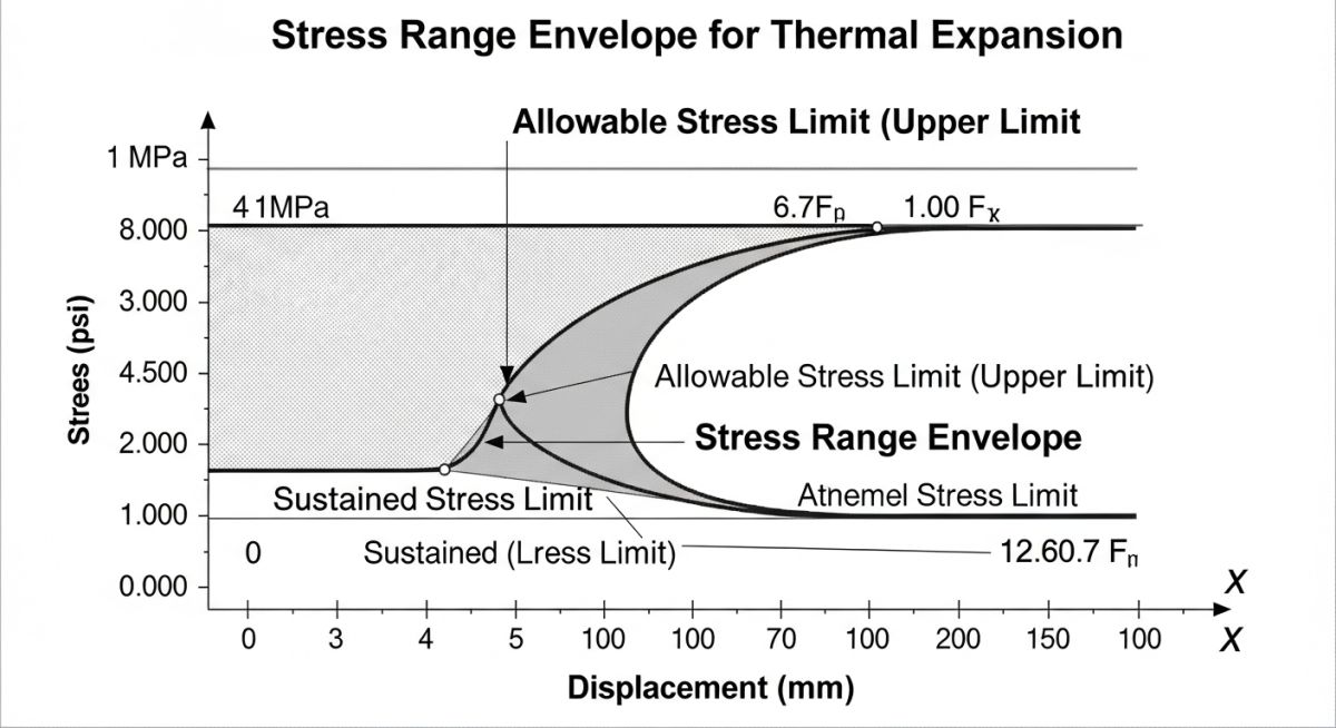
The allowable displacement stress range (S_A) is governed by the classic equation:
Where:
• f is the stress range reduction factor (fatigue factor), which decreases as the number of design cycles increases.
• S_c is the basic allowable stress of the material at the minimum metal temperature (cold state).
• S_h is the basic allowable stress of the material at the maximum metal temperature (hot state).
If the sustained stress (S_L) is low, the code allows us to add the unused margin of sustained stress to the allowable displacement stress range. This is known as the “liberal allowable stress range” (S_A):
This liberal equation is a powerful tool. In my design reviews, when a piping system fails the standard stress range check, I always verify if the software has been configured to apply this liberal allowable. It often resolves stress issues without requiring expensive piping rerouting or additional expansion joints.
The table below outlines typical allowable stress values and calculated stress ranges for common piping materials under standard operating conditions. These values demonstrate how temperature and material selection influence the allowable limits.
| Material Spec | Cold Allowable S_c (psi) | Hot Allowable S_h (psi) | Fatigue Factor (f) | Standard S_A (psi) | Liberal S_A (psi) [S_L = 8,000 psi] |
|---|---|---|---|---|---|
| ASTM A106 Gr. B | 20,000 | 18,900 (at 500°F) | 1.0 (7,000 cycles) | 29,725 | 40,625 |
| ASTM A312 TP304 | 20,000 | 16,200 (at 600°F) | 1.0 (7,000 cycles) | 29,050 | 37,250 |
| ASTM A335 P11 | 20,000 | 18,900 (at 700°F) | 0.9 (14,000 cycles) | 26,752 | 36,562 |
This matrix maps the core technical entities, code references, and physical parameters required to execute a compliant stress range analysis.
| Technical Entity | ASME B31.3 Reference | Physical Parameter | Verification Method |
|---|---|---|---|
| Displacement Stress Range (S_E) | Paragraph 319.4.4 | Bending and torsional stress combination | Verify SIFs at tees, elbows, and nozzles |
| Allowable Stress Range (S_A) | Paragraph 302.3.5 | Maximum permissible cyclic stress limit | Compare S_E against S_A or liberal S_A |
| Fatigue Reduction Factor (f) | Table 302.3.5 | Cycle-dependent reduction multiplier | Audit total expected thermal cycles over design life |
Piping Stress Range Verification Checklist
Before signing off on any piping stress analysis report, I run through a strict verification protocol. This checklist is designed to catch the subtle modeling errors that software packages will not flag as errors, but which will cause physical piping failures in the field.
Calculation Audit Checkpoints
-
Verify Temperature Profiles: Ensure that the ambient installation temperature and the maximum/minimum operating temperatures are correctly defined. Do not forget to include steam-out or solar radiation effects if applicable.
-
Audit Fatigue Cycle Assumptions: Confirm that the fatigue reduction factor (f) matches the actual expected thermal cycles of the plant. A default value of 1.0 is only valid up to 7,000 cycles.
-
Check Support Friction Coefficients: Ensure that friction is modeled on all sliding supports. Omitting friction artificially reduces the calculated stress range at anchors and equipment nozzles.
-
Validate SIFs at Branch Connections: Double-check that the correct Stress Intensification Factors (SIFs) are applied to tees, weldolets, and fabricated branches per ASME B31.3 Appendix D.
-
Confirm Load Case Setup: Verify that the displacement stress range is calculated as the algebraic difference between the hot operating case and the cold shutdown case, not as a standalone thermal case.
Field Case Study: Real-World Application
The Problem: Cracking at a High-Pressure Steam Tee
At a combined-cycle power plant, a 12-inch ASTM A335 P22 high-pressure steam line experienced recurring cracking at a welded branch connection. The plant operated in a cycling regime, starting up and shutting down daily. The original stress analysis report indicated that the displacement stress range was within the allowable limits. However, the analyst had modeled the system using a static thermal case that assumed a uniform temperature distribution, completely ignoring the transient thermal gradients that occurred during rapid startup.
The Outcome: Re-Analysis and Redesign
I was brought in to audit the system. I rebuilt the stress model in CAESAR II, incorporating the transient thermal profiles and the correct fatigue reduction factor for 15,000 cycles (f = 0.9). The re-analysis revealed that the actual displacement stress range at the tee was 45% higher than the allowable limit.
To resolve the issue, we redesigned the piping layout by adding a 3D expansion loop to increase flexibility and replaced the standard welded tee with a forged integrally reinforced outlet. This modification reduced the displacement stress range to well within the ASME B31.3 allowable limits, and the system has operated without failure ever since.
This case highlights why we cannot rely blindly on software outputs. As engineers, we must understand the physical behavior of the piping system and ensure our mathematical models accurately represent reality.
Frequently Asked Engineering Questions
What is the difference between sustained stress and displacement stress range?
How does ASME B31.3 define the liberal stress range?
Why is the fatigue reduction factor (f) important?
Can CAESAR II automatically calculate the correct stress range?
How do friction coefficients affect the displacement stress range?
What happens if a piping system exceeds the allowable stress range?
===FAQ_BLOCK===

Complete Course on
Piping Engineering
Check Now
Key Features
- 125+ Hours Content
- 500+ Recorded Lectures
- 20+ Years Exp.
- Lifetime Access
Coverage
- Codes & Standards
- Layouts & Design
- Material Eng.
- Stress Analysis