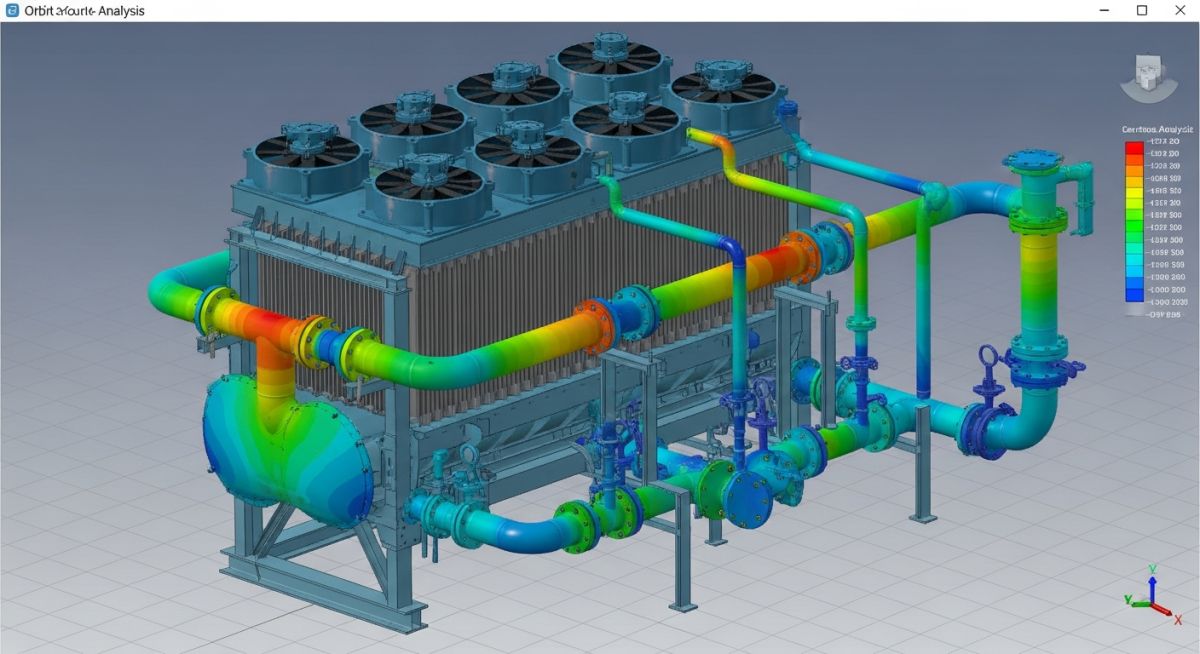
Air Cooler Piping Stress Analysis Using Caesar II Modeling Guide
In my 20 years of piping engineering experience, few equipment interfaces present as many structural challenges as the Air Fin Cooler (AFC). These massive units, often perched high on pipe racks, are subjected to extreme process temperatures, wind loads, and solar radiation. When you connect stiff, heavy-walled process piping to the relatively flexible header boxes of an air cooler, the resulting thermal expansion can easily overload the equipment nozzles.
I have seen many junior engineers struggle with this interface because they treat the air cooler as a simple rigid anchor. This mistake leads to failed nozzle load checks, warped header boxes, and flange leaks during commissioning. To prevent these field failures, we must build highly accurate Caesar II models that account for the physical stiffness of the header, vendor-specified thermal displacements, and the structural behavior of fixed versus split headers.
Key Engineering Takeaways
- Understand how to extract and apply vendor-certified thermal displacements at the nozzle interface.
- Master the step-by-step modeling of fixed and split header configurations using Caesar II C-nodes.
- Learn to design piping layouts that satisfy the strict allowable load limits defined by API Standard 661.
- Discover how to balance thermal flexibility with structural support on elevated pipe rack installations.
Documents for Air Cooler Piping Stress Analysis
Before opening Caesar II, you must gather a specific set of engineering documents. Working with incomplete data is a major risk that often results in costly design iterations. In my practice, I never begin the analysis without securing the following certified documents:
- Vendor General Arrangement (GA) Drawings: These drawings provide the exact physical dimensions of the air cooler, nozzle coordinates, nozzle sizes, flange ratings, and the dry and operating weights of the bundle.
- Nozzle Allowable Load Table: While API Standard 661 Appendix C defines standard allowable forces and moments, vendors often provide custom, higher allowable limits based on their structural design.
- Process Data Sheets: These sheets specify the design temperature, operating temperature, design pressure, and fluid density, which are critical for calculating thermal expansion and hydrostatic test loads.
- Piping Isometric Drawings and Plot Plans: These documents show the routing of the inlet and outlet manifolds, support locations, and the spatial relationship between the air cooler and the pipe rack.
Executing Air Cooler Piping Stress Analysis Steps
Once the documents are verified, the modeling phase begins. The goal is to simulate the physical interaction between the piping system and the air cooler. This requires a systematic approach to modeling the piping, the nozzle connections, and the equipment support structure.
Modeling Air Cooler in Caesar II
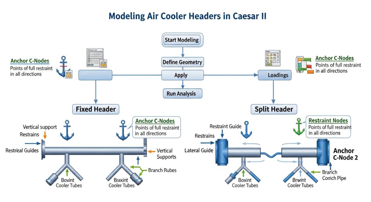
To model an air cooler accurately, we must represent the physical distance from the nozzle flange face to the centerline of the header box, and from the header box to the structural anchor point. This is achieved by using a combination of piping elements, rigid elements, and anchor restraints with C-nodes.
Modeling Up to the Header Connection
Start by modeling the inlet or outlet piping manifold. Model the run from the main process line, through any expansion loops, up to the flange connection at the air cooler nozzle. Ensure that the material properties, corrosion allowances, and insulation weights are entered correctly for these piping elements.
Modeling After Defining C-Node Anchor
At the nozzle flange face, define an anchor restraint. However, this is not a standard rigid anchor to the ground. You must assign a C-node (connecting node) to this anchor. The C-node acts as the bridge that transfers the thermal movement of the air cooler header box to the piping system. From this nozzle node, model a rigid element representing the nozzle neck length and half the header box depth, ending at the header centerline.
Modeling Part Of Equipment Restraint Nodes
The air cooler bundle is supported on a steel structure. This support acts as the physical anchor for the equipment. In Caesar II, we model this by placing an anchor at the header centerline node (the C-node). This anchor represents the structural restraint of the air cooler frame. If the vendor provides specific stiffness values for the header box support, these must be entered into the restraint configuration.
Modeling Split Header C-Node Anchors
Air coolers often utilize split headers to accommodate differential thermal expansion between the hot inlet tubes and the cooler outlet tubes. When modeling a split header, you cannot treat the entire bundle as a single rigid body. You must model each header section independently, applying distinct thermal displacements to the respective C-nodes of each nozzle group based on their local operating temperatures.
Stress Analysis with Known Vendor Displacements
When the air cooler vendor provides explicit thermal displacements at the nozzles, these values must be entered directly into the Caesar II model. These displacements represent the thermal growth of the equipment itself.
The thermal expansion of the header box can be calculated using the standard linear thermal expansion formula:
Where:
• dL is the thermal expansion (mm).
• L is the distance from the equipment anchor point to the nozzle centerline (mm).
• alpha is the mean coefficient of thermal expansion of the header material (mm/mm/°C).
• dT is the temperature difference between the operating temperature and the ambient installation temperature (°C).
In Caesar II, these calculated or vendor-provided displacements are entered as “Thermal Anchor Movements” on the C-nodes. This ensures that when the software runs the thermal load cases (e.g., T1, T2), it forces the piping connection to move by the exact amount the air cooler expands, revealing the true stress state of the system.
In my field audits, I have frequently discovered models where the air cooler nozzle was modeled as a simple, stationary rigid anchor. This completely ignores the thermal growth of the air cooler bundle, which can be 3 mm to 8 mm in high-temperature services. Ignoring this displacement leads to underestimated piping stresses and overloaded nozzles, which can cause catastrophic flange leaks or structural buckling of the air cooler frame. Always insist on obtaining vendor displacements or calculate them manually.
The following tables provide the standard allowable nozzle loads based on API Standard 661 and the technical mapping of Caesar II modeling elements to physical components.
| Nozzle Size (NPS) | Allowable Axial Force (Fx) (N) | Allowable Shear Force (Fy) (N) | Allowable Shear Force (Fz) (N) | Allowable Torsional Moment (Mx) (N·m) | Allowable Bending Moment (My) (N·m) | Allowable Bending Moment (Mz) (N·m) |
|---|---|---|---|---|---|---|
| 4 | 2,220 | 4,450 | 3,560 | 1,360 | 2,030 | 1,360 |
| 6 | 3,340 | 6,670 | 5,340 | 2,710 | 4,070 | 2,710 |
| 8 | 4,450 | 8,900 | 7,120 | 4,750 | 6,780 | 4,750 |
| 10 | 5,560 | 11,120 | 8,900 | 7,460 | 10,170 | 7,460 |
| 12 | 6,670 | 13,340 | 10,680 | 10,850 | 14,910 | 10,850 |
| Physical Component | Caesar II Element Type | Boundary Condition / Input | Applicable Code / Standard |
|---|---|---|---|
| Inlet/Outlet Piping | Standard Pipe Element | Operating Temp, Pressure, Corrosion Allowance | ASME B31.3 |
| Nozzle Flange Connection | Flange Element / Rigid Element | Flange Weight, Gasket Dimensions | ASME B16.5 |
| Header Box Thermal Growth | C-Node Anchor | Prescribed Displacements (DX, DY, DZ) | API Standard 661 |
| Equipment Support Frame | Structural Restraints | Stiffness Values, Guide Restraints | AISC Steel Construction Manual |
Site Verification for Air Cooler Piping
Even the most perfect Caesar II model is useless if the field installation does not match the design. In my role as a lead auditor, I perform rigorous site walkdowns before hydrotesting. Use this checklist to verify the physical installation against your stress analysis model:
Field Verification Checkpoints
-
Spring Hanger Presets: Verify that all variable or constant spring hangers near the air cooler nozzles have their travel stop pins intact during piping erection and hydrotesting.
-
Structural Clearances: Ensure there is a minimum of 50 mm clearance between the air cooler header box and any adjacent structural steel to allow for unobstructed thermal expansion.
-
Flange Alignment: Check that the piping flange faces are perfectly parallel to the air cooler nozzle flanges before bolt-up to prevent initial assembly stresses.
-
Guide Restraint Gaps: Confirm that the physical gaps on piping guides match the Caesar II design (typically 1.5 mm to 3 mm on each side) to prevent binding during thermal growth.
-
Expansion Loop Orientation: Verify that the physical orientation of the 3D expansion loops matches the stress isometric, ensuring no structural obstructions block their movement.
Field Case Study: Real-World Application
During the commissioning of a diesel hydrotreating unit in a major refinery, the 12-inch inlet manifold of a split-header air cooler experienced severe flange leakage. The process operating temperature was 210°C. The original stress analysis had modeled the air cooler nozzles as rigid anchors with zero thermal displacement. When the system reached operating temperature, the actual thermal expansion of the split-header box pushed the nozzles outward, causing the bending moments to exceed the API Standard 661 limits by 280%, resulting in flange misalignment and immediate hydrocarbon leakage.
I was called to the site to resolve the issue. We immediately re-modeled the system in Caesar II, replacing the rigid anchors with C-nodes and applying the vendor’s certified thermal displacements (4.2 mm of lateral expansion). To absorb this movement, we modified the piping layout by adding a 3D expansion loop directly upstream of the manifold and replaced two rigid supports with variable spring hangers. The re-analysis showed that nozzle loads were reduced to 65% of the API 661 allowable limits. The physical modifications were implemented on-site, and the unit has operated leak-free for the past five years.
This case highlights the absolute necessity of modeling the physical reality of the equipment. Assuming a rigid anchor on high-temperature equipment is a shortcut that almost always leads to field failures.
Frequently Asked Engineering Questions
Why is API 661 Appendix C used for air cooler nozzle loads?
What is the difference between modeling a fixed header and a split header?
How do you handle wind and seismic loads on air cooler piping?
When should variable spring hangers be used near air cooler nozzles?
How do you obtain vendor displacements if they are not on the GA drawing?
Can we exceed API 661 allowable nozzle loads?
===FAQ_BLOCK===

Complete Course on
Piping Engineering
Check Now
Key Features
- 125+ Hours Content
- 500+ Recorded Lectures
- 20+ Years Exp.
- Lifetime Access
Coverage
- Codes & Standards
- Layouts & Design
- Material Eng.
- Stress Analysis

