Table of Contents
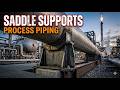
What is a Pipe Saddle and How to Design It
In my 20 years of troubleshooting piping systems, I have seen countless pipeline failures caused by localized stress concentration at support points. When you are dealing with large-diameter, thin-walled lines, a standard hanger or bare shoe simply will not cut it. That is where the pipe saddle becomes your primary line of defense. Let me walk you through how these critical components function, how we design them to prevent structural buckling, and how to select the right configuration for your plant.
Key Engineering Takeaways
- Saddles distribute heavy loads over a 120-degree arc to prevent localized pipe wall buckling.
- Integrating a wear plate or reinforcing pad (re-pad) prevents galvanic corrosion and isolates the carrier pipe from structural welds.
- Proper design must account for thermal expansion to prevent the saddle from binding on the structural steel support.
Why Use a Pipe Saddle in Piping Systems
Pipe Saddle Application: The primary application of a pipe saddle is to prevent localized pipe wall deformation and stress concentration by distributing the operating weight of the pipeline over a wider surface area in accordance with ASME B31.3 design guidelines.
When a heavy pipeline rests directly on a structural beam, the contact area is extremely small. This creates high localized point loads. For thin-walled pipes, this concentrated force can exceed the yield strength of the material, leading to localized buckling or “crimping.”
By utilizing a pipe saddle, we wrap the lower portion of the pipe—typically spanning an arc of 120 degrees. This design increases the contact area exponentially. In my experience, using a saddle is the most cost-effective way to maintain structural integrity without increasing the wall thickness of the entire pipeline run.
Saddle Stress Calculations and Design Parameters
To design a safe saddle support, we must calculate the localized longitudinal and circumferential stresses. We rely on the modified Zick analysis method for large-diameter lines. The circumferential bending stress at the horn of the saddle is calculated using this formula:
Where:
• W = Total load on the saddle support (Newtons)
• t = Thickness of the pipe wall (mm)
• b = Width of the saddle (mm)
• L = Length of the pipe span (mm)
• K1, K2 = Dimensionless coefficients based on the saddle support angle (typically 120 degrees)
The calculated stress must not exceed the allowable stress limit defined by ASME B31.3. If the stress is too high, we must either increase the saddle width (b) or add a reinforcing wear plate.
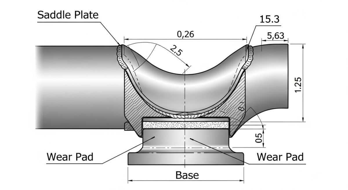
Standard Dimensions of a Pipe Saddle Support
Pipe Saddle Dimensions: Standard dimensions for pipe saddles are governed by MSS SP-58 and ASME B31.3 to ensure adequate contact area and load distribution across various nominal pipe sizes.
| Nominal Pipe Size (NPS) | Saddle Angle (Degrees) | Saddle Width (mm) | Wear Plate Thickness (mm) | Max Recommended Load (kN) |
|---|---|---|---|---|
| 6 inch | 120 | 150 | 6 | 25 |
| 12 inch | 120 | 200 | 8 | 55 |
| 18 inch | 120 | 250 | 10 | 90 |
| 24 inch | 120 | 300 | 12 | 140 |
| Component | Material Specification | Applicable Code | Primary Function |
|---|---|---|---|
| Saddle Base Plate | ASTM A36 / A516 Gr. 70 | ASME B31.3 | Transfers load to structural steel |
| Wear Plate (Pad) | Matches Carrier Pipe Material | MSS SP-58 | Prevents wear and galvanic corrosion |
| Saddle Ribs / Gussets | ASTM A36 | AISC Steel Construction | Provides structural stiffness to saddle |
How to Inspect a Pipe Saddle Installation
Pipe Saddle Inspection: Field inspection of pipe saddles requires verifying weld integrity, saddle alignment, and clearance for thermal expansion to prevent localized stress failures under operating conditions.
During my site walkdowns, I frequently find saddles that were welded incorrectly or completely restricted from moving. Use this checklist on your next project to ensure the installation matches the engineering design.
Field Inspection Checkpoints
-
Material Verification: Ensure the wear plate material matches the carrier pipe specification to prevent galvanic corrosion. -
Weep Hole Check: Verify that the reinforcing pad has a threaded weep hole (typically 1/4 inch NPT) and that it remains unplugged during operation to vent trapped gases. -
Weld Profile: Inspect the fillet welds connecting the wear plate to the pipe. They must be continuous and tested via dye penetrant (PT) per ASME B31.3. -
Slide Clearance: For sliding saddles, confirm there is adequate clearance on the guide plates to allow for calculated thermal growth. -
Paint and Coating: Ensure the underside of the saddle base plate is coated properly to prevent crevice corrosion at the structural steel interface.
Field Case Study: Real-World Application
Saddle Support Case Study: This field case study analyzes the structural failure of a thin-walled cooling water line and the subsequent engineering redesign using reinforced pipe saddles to restore system integrity.
The Problem
At a petrochemical plant in Texas, a 30-inch thin-walled (6mm wall thickness) carbon steel cooling water line began showing signs of localized buckling directly above the structural steel support beams. The line was resting on standard flat pipe shoes. The concentrated weight of the water-filled pipe caused the pipe wall to deform, creating a localized stress concentration that exceeded the material’s yield strength, threatening a catastrophic rupture.
The Outcome
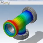
I was called in to redesign the support system. We replaced the flat shoes with 120-degree wrapped pipe saddles equipped with 10mm thick wear plates extending 50mm beyond the saddle width. This modification distributed the localized load across a much larger surface area. Finite Element Analysis (FEA) confirmed that localized stresses dropped by 65%, bringing the system well within ASME B31.3 allowable limits and preventing further deformation.
My recommendation for any large-diameter, thin-walled system (typically NPS 20 and above with a standard wall thickness) is to bypass standard shoes entirely during the design phase. Specifying a robust pipe saddle from day one saves massive field remediation costs later.
Frequently Asked Questions About Pipe Saddles
Pipe Saddle FAQs: This technical FAQ section addresses critical engineering queries regarding the selection, installation, and design limits of pipe saddles in industrial piping systems.
What is the difference between a pipe shoe and a pipe saddle?
Why is a 120-degree angle standard for pipe saddles?
Do I need to weld the pipe saddle to the carrier pipe?
What is the purpose of the weep hole in a pipe saddle wear plate?
Can we use carbon steel saddles on stainless steel piping?
How does thermal expansion affect pipe saddle design?
===FAQ_BLOCK===
Complete Course on
Piping Engineering
Check Now
Key Features
- 125+ Hours Content
- 500+ Recorded Lectures
- 20+ Years Exp.
- Lifetime Access
Coverage
- Codes & Standards
- Layouts & Design
- Material Eng.
- Stress Analysis

📚 Recommended Resources: pipe saddle
Read these Guides
- 📄 Various Types of Pipe Clamps for Piping and Plumbing Industry
- 📄 Introduction to FRP Pipes: Properties, Applications, Specifications, Codes, Joining & More
- 📄 Ultimate Guide to U-Bolt Pipe Support: Types, ASME Installation, and Field Applications
- 📄 Pipe Fabrication Shops: Shop vs. Site Fabrication in Oil and Gas


Related posts:
![Industrial piping manifold showing different types of pipe joints including flanged and welded connections.]()
Mastering the Core Types of Pipe Joints in Industrial Piping
![CNC rotary draw tube bending machine shaping a stainless steel pipe in a manufacturing facility.]()
What is Tube Bending? Working, Types, and Industrial Applications
![Cross-section comparison of a metallurgically bonded clad pipe and a mechanically bonded lined pipe.]()
What is Cladded Pipe? Difference Between Clad and Lined Pipe
![Conceptual illustration of digital technical data exchange between an engineering office and a process equipment vendor.]()
How to Manage Technical Information Exchange With Process Equipment Vendors
![3D piping stress analysis of a Smart Tee model in START-PROF software.]()
Mastering Smart Tee Model Considerations in START-PROF Stress Analysis
![Modern industrial compressed air system installation with rotary screw compressors and receiver tanks in a clean facility.]()
Designing a Compressed Air System for Maximum Industrial Efficiency