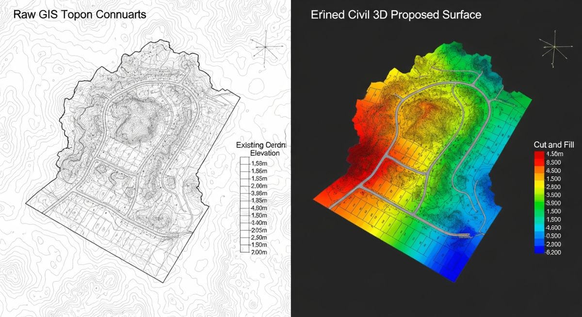
How to Optimize Cut and Fill Using Civil 3D and GIS
In my two decades of managing large-scale industrial site developments, I have found that the most significant cost overruns often stem from poor earthwork planning. When we fail to properly optimize cut and fill using Civil 3D and GIS, we end up paying for unnecessary off-site disposal or, worse, importing expensive fill material that could have been avoided through intelligent grading design.
This guide focuses on the technical rigor required to transform raw survey data into a balanced, cost-effective site model. By leveraging GIS-integrated terrain data and the powerful surface modeling tools within Civil 3D, we can simulate multiple grading scenarios to minimize haulage distances and maximize on-site material reuse.
Key Takeaways for Site Grading Efficiency:
- Integrate high-fidelity GIS data to establish accurate existing ground surfaces.
- Utilize Civil 3D volume dashboards for real-time feedback on grading adjustments.
- Implement iterative design loops to minimize the net earthwork balance.
- Reduce project haulage costs by optimizing site drainage and platform elevations.
How to Optimize Cut and Fill Using Civil 3D and GIS
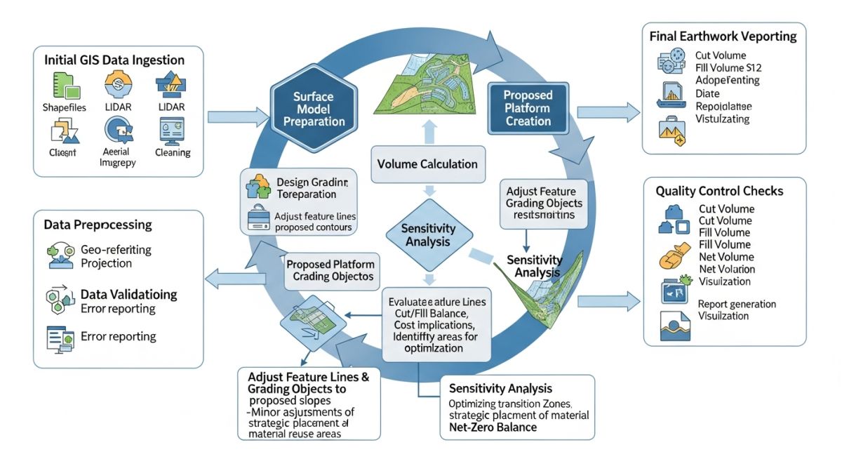
Surface Model Preparation: The foundation of any successful earthwork project lies in the integrity of the Digital Terrain Model (DTM). Before performing any calculations, I ensure that the existing surface is built from high-density point clouds or GIS-derived contours that meet ASPRS accuracy standards.
When importing GIS data, I always verify the coordinate system transformation to prevent horizontal and vertical shifts that could invalidate volume reports. Once the existing surface is locked, the proposed platform creation begins by defining feature lines that represent the breaklines of the site, such as building pads, road crowns, and retention pond embankments.
Mathematical Foundations of Volume Calculation
Civil 3D utilizes the Average End Area method or the Grid Volume method to calculate earthwork. The volume between two surfaces is defined by the integral of the difference in elevation over the site area. For a given cross-section, the area of cut or fill is calculated as:
Volume = (Area1 + Area2) / 2 * Distance
In my experience, the Grid Volume method is superior for complex, non-linear grading designs because it samples the surface at a user-defined interval, providing a more granular view of the cut and fill distribution. I typically set the grid interval to 5 meters for preliminary design and refine it to 1 meter for final construction documentation.
Technical Warning: Shrinkage and Swell Factors
Never assume a 1:1 ratio between cut and fill volumes. You must apply a soil compaction factor (shrinkage) or a bulking factor (swell) based on the geotechnical report. For clay-heavy soils, I often apply a 15% shrinkage factor to the cut volume to ensure the final site grade meets the design elevation after compaction.
To achieve a balanced site, I use the Civil 3D Grading Optimization tool to automatically adjust feature line elevations within specified constraints. By setting a target net volume of zero, the software iterates through thousands of elevation combinations to find the most efficient grading solution. This process significantly reduces the need for manual trial-and-error, allowing the engineering team to focus on site drainage and geotechnical stability.
Finally, I perform a sensitivity analysis by varying the platform elevation by plus or minus 100mm. This reveals how sensitive the earthwork balance is to minor design changes, which is vital for projects with tight budget constraints or limited on-site storage capacity for excess material.
Earthwork Optimization Trade-offs: The implementation of automated grading tools in Civil 3D provides significant efficiency gains but requires a disciplined approach to data management and geotechnical parameter validation.
Advantages
- Drastic reduction in manual calculation time for complex grading.
- Real-time visualization of cut and fill heat maps.
- Improved accuracy in estimating haulage and material costs.
- Seamless integration with BIM workflows for multi-disciplinary coordination.
- Ability to simulate “what-if” scenarios for rapid design iteration.
Disadvantages
- High dependency on the quality of initial GIS survey data.
- Potential for “black box” errors if constraints are poorly defined.
- Requires advanced training to interpret and validate automated results.
- Significant computational load for large-scale site models.
- Risk of ignoring localized geotechnical anomalies during automation.
Industrial Site Grading Applications: The following sectors rely heavily on precise earthwork balancing to maintain project viability and environmental compliance.
Large-Scale Solar Farm Development
Solar arrays require vast, relatively flat surfaces to maximize energy capture. By using Civil 3D to optimize the grading of thousands of acres, we minimize the need for imported gravel and soil, significantly lowering the levelized cost of energy for the project.
Petrochemical Plant Infrastructure
Industrial plants require complex drainage networks and heavy-duty foundations that demand precise elevation control. We use iterative grading to ensure that the site remains above the 100-year flood level while keeping the cut and fill volumes within the plant’s internal site boundaries.
Highway and Interchange Construction
Linear infrastructure projects involve massive earth movement across varying terrain. Civil 3D allows us to balance the cut from deep road cuts with the fill required for embankments, minimizing the environmental impact and the cost of transporting soil across long distances.
Mining Site Reclamation
Post-mining land restoration requires re-contouring the landscape to match natural drainage patterns. Our optimization workflow ensures that the final landform is stable and erosion-resistant, using the existing overburden to fill voids and create sustainable slopes.
When performing earthwork volume calculations in Civil 3D, the accuracy of your output is fundamentally tied to the methodology applied to the Digital Terrain Model (DTM). Engineers must distinguish between the Average End Area method, which is standard for corridor-based linear projects, and the Grid Volume method, which is often preferred for complex site grading platforms where surface complexity is high.
The following table outlines the critical parameters that influence volume precision. I consistently advise my team to verify the “Shrinkage and Swell” factors against local geotechnical reports, as these coefficients can alter the net balance by 15% or more if miscalculated. Always ensure your surface boundaries are tightly defined to prevent “null” data from skewing the TIN (Triangulated Irregular Network) calculations.
| Parameter | Methodology | Standard Reference |
|---|---|---|
| Average End Area | Cross-section interpolation | ASCE Manual 45 |
| Grid Volume | Cell-based elevation difference | ASTM D698 |
| TIN Volume Surface | Composite surface subtraction | ISO 19157 |
By utilizing a TIN Volume Surface, you create a dynamic model that updates automatically as you adjust your grading feature lines. This real-time feedback loop is essential for achieving a balanced site where cut volumes are repurposed as fill, thereby minimizing off-site disposal costs and environmental impact.
The integration of GIS data with Civil 3D requires a robust mapping of entities to ensure coordinate system consistency and data integrity. In my experience, the most common failure point in large-scale grading projects is the misalignment between the GIS-derived existing ground surface and the CAD-based proposed design surface.
This matrix serves as a technical reference for mapping project entities to their respective engineering standards. By standardizing these inputs, you reduce the risk of “surface tearing” or interpolation errors that occur when importing disparate data formats like LiDAR point clouds or legacy survey contours into a unified design environment.
| Entity Type | GIS/CAD Source | Standard/Protocol |
|---|---|---|
| LiDAR Point Cloud | LAS/LAZ File | ASPRS LAS 1.4 |
| Feature Lines | Civil 3D Grading | ISO 10303 |
| Geospatial Raster | GeoTIFF/DEM | OGC WCS |
Maintaining this mapping structure ensures that your Autodesk workflows remain compliant with BIM (Building Information Modeling) standards. Always validate the vertical datum (e.g., NAVD88) before finalizing your volume reports to avoid catastrophic elevation discrepancies.
Before finalizing any earthwork design, I conduct a rigorous site verification process. This checklist is designed to catch common errors in surface modeling and volume balancing that often lead to costly change orders during the construction phase. Use these checkpoints to ensure your design is both constructible and economically optimized.
-
01.
Coordinate System Validation: Confirm that the GIS source data and the Civil 3D drawing share an identical projection system to prevent horizontal shift errors. -
02.
Surface Boundary Integrity: Ensure all proposed grading surfaces have defined boundaries to prevent the software from triangulating across “void” areas. -
03.
Shrinkage/Swell Factor Application: Verify that the soil compaction factors are applied to the net volume calculation based on the specific geotechnical report for the site. -
04.
Feature Line Breaklines: Check that all feature lines are set to “Breakline” status to force the TIN surface to honor the design geometry accurately. -
05.
Volume Report Audit: Run a comparative analysis between the “Grid” and “TIN” volume methods to ensure the variance is within the acceptable 2% threshold.
By strictly adhering to these verification steps, you minimize the risk of “daylighting” errors where the proposed slope fails to meet the existing ground at the intended location. Always document your surface creation process in a design log to facilitate future audits or project handovers.
The Challenge: Unbalanced Grading in High-Relief Terrain
- Initial design resulted in a 40,000 cubic yard excess of cut material.
- Haulage costs were projected to exceed the project budget by 25%.
- Existing GIS data lacked the vertical resolution required for precise slope toe placement.
- TIN surface artifacts caused “spikes” in the volume calculation, leading to inaccurate reporting.
The Outcome: Optimized Grading and Cost Reduction
- Adjusted platform elevations by 0.5 meters to achieve a near-zero net balance.
- Implemented dynamic feature line grading to reduce total earthwork by 18%.
- Integrated high-resolution drone-based LiDAR to refine the existing ground surface model.
- Reduced total project haulage costs by approximately 35% through on-site material reuse.
My recommendation for similar projects is to prioritize the “balancing” phase early in the design cycle. By treating the site as a closed system, you can manipulate the grading platform to act as a storage vessel for cut material, effectively eliminating the need for external spoil sites.
How do I handle soil shrinkage in Civil 3D?
Soil shrinkage and swell factors are critical for accurate volume reporting. In Civil 3D, you apply these factors within the “Earthwork” settings of your volume surface properties:
- Define the Cut Factor to account for the expansion of soil when excavated.
- Define the Fill Factor to account for the compaction of soil when placed.
- Always reference the geotechnical report for specific soil types (e.g., clay vs. sand).
- Ensure these factors are applied to the final volume report to reflect the “bank” vs. “loose” volume states.
Why does my TIN surface show gaps?
Gaps in a TIN surface usually indicate that the triangulation process is failing to connect points across a specific boundary or that the data density is insufficient in that area. To resolve this, I recommend the following:
- Check the “Maximum Triangle Length” setting in the surface properties.
- Add “Boundary” definitions to the surface to force the triangulation to stop at the site perimeter.
- Verify that your feature lines are properly closed and have valid elevation data.
- Use the “Swap Edge” command to manually correct triangulation artifacts in critical grading areas.
What is the difference between Grid and TIN volumes?
The choice between Grid and TIN volume methods depends on the required precision and the nature of the surface data. The Grid method samples the surface at fixed intervals, which is computationally efficient but can miss subtle elevation changes between grid points.
- TIN volumes use the exact triangulation of the surface, making them significantly more accurate for complex grading.
- Grid volumes are often used for preliminary estimates where speed is prioritized over absolute precision.
- For final design and earthwork balancing, I exclusively use the TIN Volume Surface method.
- Always validate your choice against the project’s specific accuracy requirements defined in the contract documents.
How do I integrate GIS data into Civil 3D?
Integrating GIS data requires a clear understanding of coordinate systems and data formats. I typically use the “Map Import” or “Data Connect” features within Civil 3D to bring in shapefiles or raster data.
- Ensure the drawing coordinate system is set before importing any GIS data.
- Use “Data Connect” for live links to GIS databases, which allows for real-time updates.
- Convert GIS features to Civil 3D objects (like surfaces or feature lines) to enable advanced grading tools.
- Always verify the vertical datum of the GIS data to ensure it matches your project’s survey control.
Can I automate the balancing of cut and fill?
While Civil 3D does not have a single “balance” button, you can automate the process using the “Grading Optimization” tool. This module allows you to set constraints and objectives, such as “minimize earthwork” or “achieve zero net balance,” and the software will iterate the design to meet these goals.
- Define your grading zones and constraints (e.g., maximum slope, minimum elevation).
- Run the optimization engine to generate a proposed surface that meets your criteria.
- Review the results and manually refine the feature lines if necessary.
- This approach significantly reduces the time required for iterative design cycles.
What are the best practices for surface modeling?
Surface modeling is the foundation of all earthwork calculations. To ensure accuracy, I follow these core principles:
- Keep your surface definitions clean by removing unnecessary data points.
- Use breaklines to define ridges, valleys, and curbs accurately.
- Always use a “Data Shortcut” to reference surfaces across multiple project files.
- Regularly audit your surface for “spikes” or “holes” that could indicate bad survey data or modeling errors.
Complete Course on
Piping Engineering
Check Now
Key Features
- 125+ Hours Content
- 500+ Recorded Lectures
- 20+ Years Exp.
- Lifetime Access
Coverage
- Codes & Standards
- Layouts & Design
- Material Eng.
- Stress Analysis
