8 Engineering Studies for Effective Cut and Fill Optimization
In my two decades of experience managing large-scale industrial projects, I have seen countless budgets spiral out of control simply because the initial site grading strategy ignored the fundamental relationship between soil mechanics and site drainage. Achieving true cut and fill optimization is not merely about moving dirt from point A to point B; it is an intricate engineering puzzle that requires a deep understanding of the site’s natural behavior.
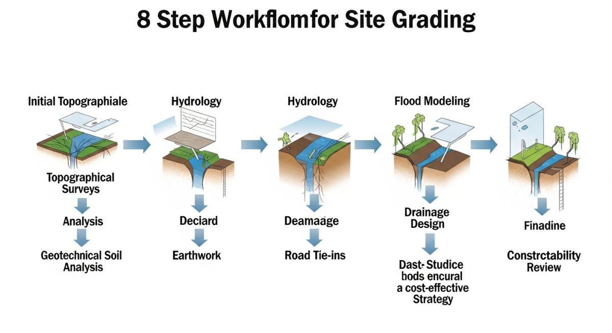
When we fail to integrate geotechnical data with our mass haul plans, we often end up with “unsuitable” material that requires expensive stabilization or off-site disposal. This guide breaks down the eight critical studies required to master your site grading, ensuring your project remains both cost-effective and structurally sound from the first day of mobilization.
Key Takeaways for Site Grading Success:
- Integrate geotechnical soil profiles early to avoid costly material re-handling.
- Use hydrological modeling to define drainage paths before finalizing grading elevations.
- Prioritize on-site material reuse to eliminate expensive import/export logistics.
- Conduct constructability reviews to align grading plans with heavy equipment access.
Technical Deep-Dive: Cut and Fill Optimization Strategies
Cut and Fill Optimization Engineering: The application of advanced surveying and soil mechanics to minimize net earthwork volumes through precise elevation modeling and material suitability analysis.
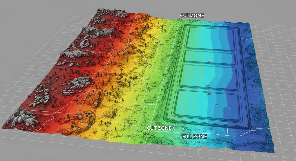
To achieve optimal earthwork balance, we must first establish a high-fidelity digital terrain model (DTM). In my experience, the accuracy of your cut and fill optimization is directly proportional to the density of your topographical survey data. We utilize LiDAR and RTK-GPS to capture sub-centimeter variations, which are then processed through software like Civil 3D to calculate the theoretical volumes of cut and fill required to reach the design grade.
Geotechnical Integration and Soil Suitability
The most common failure in site grading is treating all “cut” material as “fill” material. We must perform a comprehensive geotechnical investigation, typically following ASTM D2487, to classify soil types. If the cut material is high-plasticity clay, it may be unsuitable for structural fill under heavy equipment foundations without significant chemical stabilization or moisture conditioning.
Field Warning: The “Bulking” Factor
Never assume a 1:1 volume ratio between cut and fill. Excavated soil undergoes “bulking” or “shrinkage” depending on its compaction characteristics. Always apply a shrinkage factor (typically 10-15% for clayey soils) to your volume calculations to avoid a deficit of material at the end of the grading phase.
Hydrological and Drainage Constraints
Site grading is fundamentally a drainage exercise. Before finalizing the mass haul plan, we must conduct a hydrological assessment to determine the 100-year flood levels. If your grading plan creates a “bowl” effect, you are inviting catastrophic failure during extreme weather events. We align our grading elevations with the site’s natural drainage basins, ensuring that all runoff is directed toward retention ponds or municipal discharge points as per ASCE 7 standards.
The calculation for required storage volume is defined by the rational method: Q = CiA, where Q is the peak runoff rate, C is the runoff coefficient, i is the rainfall intensity, and A is the drainage area. By adjusting the site grade, we can manipulate the runoff coefficient C, effectively reducing the size and cost of the required storm-water infrastructure.
Earthwork Optimization Trade-offs: The strategic evaluation of balancing site grading efficiency against the long-term operational risks and capital expenditure requirements of industrial site development.
Advantages
- Significant reduction in material import/export logistics costs.
- Minimized environmental impact by reducing heavy vehicle traffic.
- Improved site drainage performance through intentional elevation design.
- Enhanced structural integrity by matching soil types to load-bearing zones.
- Reduced project timeline by eliminating off-site material procurement.
Disadvantages
- High initial engineering cost for detailed geotechnical and hydrological studies.
- Increased complexity in site management and equipment scheduling.
- Risk of “unsuitable” soil discovery during deep excavation phases.
- Potential for prolonged permitting if drainage patterns are significantly altered.
- Sensitivity to weather-related delays during mass earthwork operations.
Industrial Site Grading Applications: The practical implementation of mass earthwork optimization across diverse sectors to ensure structural stability and regulatory compliance for heavy infrastructure.
Large-Scale Petrochemical Refineries
Refineries require massive, perfectly level pads for heavy equipment and tank farms. By optimizing cut and fill, we ensure that the structural fill meets the stringent bearing capacity requirements of API 650 while minimizing the need for imported structural fill, which can be prohibitively expensive in remote locations.
Renewable Energy Solar Arrays
Solar farms cover vast acreages where even minor grading errors can lead to significant drainage issues and panel shading. We use cut and fill optimization to create gentle, consistent slopes that facilitate natural water runoff, preventing erosion and protecting the integrity of the mounting systems over a 25-year lifespan.
Logistics and Distribution Hubs
Distribution centers rely on massive, flat concrete slabs that are highly sensitive to differential settlement. Our optimization process focuses on identifying and removing organic, compressible soils during the cut phase, replacing them with engineered fill to ensure the slab remains level and crack-free under heavy forklift traffic.
Effective cut and fill optimization relies on precise volumetric calculations derived from high-fidelity topographical data. In my experience, the accuracy of these calculations is directly proportional to the density of the survey grid and the inclusion of soil swell and shrinkage factors. When we analyze site grading, we must account for the difference between the “bank” volume (in-situ) and the “compacted” volume (final state) to avoid costly material import or export scenarios.
The following table outlines the critical parameters I monitor during the preliminary design phase. These values are essential for calculating the mass haul diagram, which dictates the movement of soil across the site. By aligning these parameters with ASTM D698 standards for moisture-density relationships, we ensure that the earthwork balance remains within the project’s economic and structural tolerances.
| Parameter | Standard/Reference | Typical Range |
|---|---|---|
| Shrinkage Factor | FHWA Earthwork Guide | 10% to 25% |
| Compaction Effort | ASTM D698 | 95% to 98% Modified Proctor |
| Swell Factor | Geotechnical Report | 5% to 15% (Rock) |
Always verify these factors against the specific soil classification found in your geotechnical report. Using generic industry averages without site-specific testing often leads to significant budget overruns during the construction phase.
Engineering a site for optimal cut and fill requires a multidisciplinary approach where topographical, geotechnical, and hydrological data streams intersect. I maintain this matrix to ensure that every design decision is cross-referenced against the relevant regulatory standards and physical site constraints. This prevents the common pitfall of designing a grading plan that is geometrically sound but geotechnically unstable or hydrologically non-compliant.
The matrix below maps the primary engineering entities to their respective governing standards. By utilizing this framework, project managers can track the maturity of each study and identify potential conflicts between, for example, drainage requirements and road tie-in elevations. This systematic approach is the hallmark of a robust civil engineering design process.
| Entity | Standard | Primary Objective |
|---|---|---|
| Topographical Survey | ASCE 38-02 | Surface Data Accuracy |
| Geotechnical Investigation | ASTM D420 | Soil Bearing Capacity |
| Hydrology Assessment | NOAA Atlas 14 | Stormwater Runoff Modeling |
Consistent application of these standards ensures that the site grading plan remains defensible during regulatory review and constructible in the field. Never bypass these mappings, as they form the foundation of your site’s long-term structural integrity.
Site Verification Protocols: Before finalizing any cut and fill optimization plan, I mandate a comprehensive site verification process. This checklist ensures that the theoretical model aligns with the physical reality of the terrain, preventing costly field adjustments during the mobilization phase.
- ✓ Benchmark Verification: Confirm all site benchmarks against local geodetic control points to ensure vertical accuracy within 5mm.
- ✓ Soil Stratigraphy Check: Validate that the depth of topsoil stripping matches the geotechnical borehole logs to prevent unexpected disposal costs.
- ✓ Hydrological Flow Paths: Inspect existing natural drainage swales to ensure the proposed grading does not create upstream ponding or downstream erosion.
- ✓ Utility Interference: Cross-reference the grading plan with existing underground utility maps, specifically looking for shallow gravity lines that limit cut depths.
- ✓ Slope Stability Review: Verify that all proposed cut slopes comply with OSHA safety standards for trenching and excavation.
Each item on this list must be signed off by the lead site engineer. In my experience, skipping the utility interference check is the most common cause of project delays. Always treat the site as a dynamic environment where the initial survey might not capture every nuance of the subsurface conditions. By performing these checks, you mitigate risk and ensure that the earthwork balance remains optimized throughout the construction lifecycle.
Field Case Study: Real-World Application
The Challenge: Unforeseen Subsurface Conditions
A large industrial site development faced a 30% deficit in fill material due to inaccurate initial geotechnical assumptions regarding soil density.
- Inadequate borehole spacing failed to identify a large pocket of organic, non-structural soil.
- The original cut and fill optimization model assumed a uniform shrinkage factor across the entire site.
- Heavy rainfall during the initial grading phase saturated the stockpiled material, rendering it unusable for structural fill.
The Outcome: Optimized Recovery and Cost Control
By implementing a revised mass haul strategy and on-site soil stabilization, we successfully recovered the project timeline and budget.
- Utilized lime-stabilization to treat the saturated soil, converting it into acceptable structural fill.
- Re-modeled the site grading to reduce the overall footprint, minimizing the total volume of required import.
- Implemented real-time GPS machine control to ensure precise lift thickness and compaction density.
My recommendation for similar projects is to always include a contingency for soil stabilization in the initial budget. Relying solely on “cut-to-fill” without a plan for poor-quality soil management is a significant risk factor in modern site development.
Frequently Asked Engineering Questions
How do I determine the correct shrinkage factor?
- Perform laboratory testing per ASTM D698 to establish the maximum dry density.
- Conduct field density tests on the existing ground to determine the in-situ unit weight.
- Calculate the ratio of the two values to derive the site-specific shrinkage factor.
- Always apply a safety margin to this factor, as field compaction efficiency rarely matches laboratory perfection.
What is the impact of hydrology on grading?
- Ensure that all finished grades promote positive drainage away from building foundations.
- Integrate detention basins into the cut and fill balance to utilize excavated material on-site.
- Verify that the peak runoff rates do not exceed the capacity of the downstream municipal infrastructure.
- Consult NOAA Atlas 14 for regional precipitation data to ensure your models are current.
How does rock excavation affect project costs?
- The “swell factor” for rock is typically higher than soil, meaning the volume of material increases significantly after excavation.
- You must account for the disposal of excess rock if it cannot be crushed and reused as structural fill.
- Geotechnical investigations should include seismic refraction surveys to accurately map the rock surface depth.
- Always include a rock excavation unit price in the contract to avoid disputes during construction.
Why is a constructability review necessary?
- It identifies potential access constraints for heavy machinery in tight site conditions.
- It verifies that the proposed slopes are achievable with standard grading equipment.
- It ensures that the sequence of operations minimizes double-handling of soil.
- It allows for the adjustment of design features that might otherwise lead to safety hazards or excessive costs.
What are the risks of poor site grading?
- Differential settlement of building foundations due to improper compaction.
- Erosion and sediment control failures leading to environmental regulatory fines.
- Increased long-term maintenance costs for pavement and drainage systems.
- Potential for structural failure of retaining walls or steep slopes.
How do I optimize road tie-in elevations?
- Ensure that the tie-in slope complies with local DOT standards for sight distance and grade transitions.
- Use the road tie-in as a control point for the entire site’s vertical design.
- Coordinate with local authorities early to confirm the required pavement section and drainage connection points.
- Minimize the need for retaining walls at the property line by adjusting the site grade to meet the road elevation naturally.
📚 Recommended Resources: Cut and Fill Optimization
Read these Guides
- 📄 Optimizing Cut and Fill Quantities for Industrial Site Development
- 📄 Calculating Cut and Fill Quantities for Efficient Civil Earthworks Projects
- 📄 Topographical Survey Explained: Essential Engineering Site Data and Deliverables
- 📄 Geotechnical and Topographical Surveys: A Complete Guide for Engineers
Complete Course on
Piping Engineering
Check Now
Key Features
- 125+ Hours Content
- 500+ Recorded Lectures
- 20+ Years Exp.
- Lifetime Access
Coverage
- Codes & Standards
- Layouts & Design
- Material Eng.
- Stress Analysis
