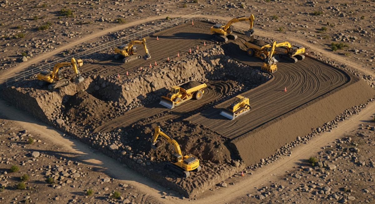
Factors Affecting Cut and Fill Quantities in Industrial Site Development
In my two decades of managing large-scale industrial projects, I have learned that the most significant budget overruns often hide beneath the surface. Calculating accurate cut and fill quantities is not merely a matter of comparing existing and proposed contours; it is a complex engineering balancing act. When we design a site, we are essentially managing a massive mass-balance equation where soil properties, drainage requirements, and structural foundations dictate the final earthwork volume.
If you ignore the nuances of swell factors, compaction ratios, or the impact of flood mitigation requirements, your initial estimates will inevitably fail. This guide breaks down the critical variables that influence your site grading strategy, ensuring your project remains both technically sound and economically viable.
Key Takeaways for Project Success:
- Understand the impact of soil shrinkage and swell factors on net volume.
- Align platform levels with flood plain requirements to minimize imported fill.
- Integrate road tie-ins early to avoid costly re-grading of site access.
- Prioritize geotechnical stability to prevent long-term settlement issues.
Technical Analysis of Cut and Fill Quantities
Earthwork Volume Management: The rigorous application of volumetric analysis to determine the net movement of soil mass, accounting for material density changes and site-specific geotechnical constraints.
When I approach a site grading plan, I start by establishing the “Balance Point.” This is the elevation where the volume of cut material equals the volume of fill material, adjusted for the compaction factor. In industrial projects, we often use the ASCE guidelines for earthwork to ensure that our site preparation meets the structural requirements of heavy equipment foundations.
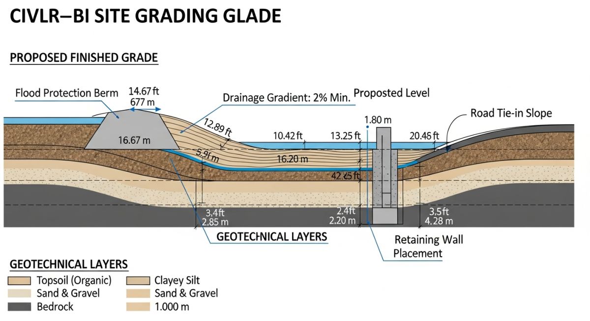
Calculating Volumetric Changes
Soil is never static. When you excavate, the material expands (swell factor), and when you place it as fill, it compresses (shrinkage factor). The formula I use for net volume is: V_net = (V_cut * S_f) – (V_fill / C_f), where S_f is the swell factor and C_f is the compaction factor. If your C_f is 0.90, you need 10% more material than the geometric volume suggests.
Field Warning: Geotechnical Variability
Never rely on a single borehole for site-wide grading. Variations in soil moisture content can change your compaction factor by up to 15% overnight. Always perform a Proctor test on-site to verify the maximum dry density before finalizing your mass-haul diagram.
Flood Requirements and Platform Levels
Industrial platforms must often sit above the 100-year flood elevation. This requirement frequently forces a “fill-heavy” design. I have seen projects where the cost of importing fill exceeded the cost of the entire foundation package. To mitigate this, we look at terracing the site or using structural retaining walls to reduce the footprint of the fill slope.
Drainage requirements also dictate your grading. A minimum slope of 0.5% to 1% is standard for industrial pads to prevent ponding. If your site is large, this slope creates a significant cumulative elevation change, which must be accounted for in your cut and fill quantities.
Grading Strategy Evaluation: A comparative assessment of mass-balance techniques and their direct impact on project lifecycle costs and structural integrity.
Advantages of Balanced Grading
- Minimizes off-site material disposal costs.
- Reduces heavy vehicle traffic on local roads.
- Optimizes site drainage by utilizing natural topography.
- Lowers carbon footprint by reducing material transport.
- Ensures consistent soil bearing capacity across the pad.
Disadvantages of Complex Grading
- High initial survey and geotechnical investigation costs.
- Risk of encountering unexpected rock or high water tables.
- Increased time requirements for mass-haul planning.
- Potential for erosion issues during the construction phase.
- Sensitivity to weather-induced moisture content changes.
Industrial Site Implementation: The practical application of earthwork engineering across diverse sectors to ensure operational safety and regulatory compliance.
Petrochemical Refinery Expansion
Refineries require massive, perfectly level platforms to support heavy pressure vessels and pipe racks. We utilize precise cut and fill calculations to ensure that the differential settlement remains within the strict tolerances required by ASME B31.3 piping standards.
Renewable Energy Solar Farms
Large-scale solar installations require extensive grading to maintain uniform tilt angles across thousands of acres. By optimizing the cut and fill, we reduce the need for expensive racking adjustments and ensure efficient water runoff management during storm events.
Mining Infrastructure Development
In mining, the focus shifts to managing massive stockpiles and tailings dams. We apply advanced volumetric modeling to ensure that the cut material from mine pits is effectively repurposed for dam embankments, significantly reducing project logistics costs.
Accurate estimation of cut and fill quantities requires a rigorous approach to volumetric analysis. In my experience, the primary source of budget overruns in industrial site development is the failure to account for soil swell and shrinkage factors during the transition from bank volume to compacted fill volume. Engineers must apply specific conversion factors based on the ASCE standards for geotechnical reporting to ensure that the mass haul diagram remains balanced throughout the project lifecycle.
The following table outlines the critical conversion coefficients and density assumptions I typically utilize when performing preliminary earthwork assessments. These values are subject to laboratory testing results, specifically the Proctor compaction tests, which dictate the final shrinkage percentage applied to the raw cut volume. Always verify these assumptions against the site-specific geotechnical report before finalizing the earthwork procurement strategy.
| Material Type | Swell Factor | Shrinkage Factor | Compaction Target |
|---|---|---|---|
| Loose Sand/Gravel | 1.10 – 1.15 | 0.90 – 0.95 | 95% Modified Proctor |
| Common Earth | 1.20 – 1.25 | 0.85 – 0.90 | 98% Standard Proctor |
| Stiff Clay | 1.30 – 1.40 | 0.80 – 0.85 | 95% Standard Proctor |
| Blasted Rock | 1.50 – 1.65 | 1.00 – 1.05 | Vibratory Roller |
Managing the interface between civil design and geotechnical constraints requires a structured mapping of physical parameters to their respective regulatory frameworks. I maintain this matrix to ensure that every earthwork component—from slope stability to drainage capacity—aligns with international engineering standards. This prevents the common pitfall of using generic soil assumptions in high-load industrial zones where differential settlement could compromise heavy equipment foundations.
The matrix below categorizes the primary variables influencing cut and fill quantities. By cross-referencing these entities with the relevant ASTM testing protocols, engineers can establish a defensible baseline for earthwork volumes. This systematic approach is vital for project stakeholders when evaluating the feasibility of site grading plans during the Front-End Engineering Design (FEED) phase.
| Entity | Standard | Primary Impact |
|---|---|---|
| Soil Bearing Capacity | ASTM D1196 | Foundation sizing and fill depth |
| Moisture-Density Relation | ASTM D698 | Compaction efficiency and volume |
| Slope Stability | ASCE 7 | Cut slope geometry and safety |
| Hydraulic Conductivity | ASTM D5084 | Drainage design and fill permeability |
Site Verification for Cut and Fill Quantities: A systematic validation process ensuring that topographical data, geotechnical soil profiles, and design elevations align with actual field conditions to minimize earthwork variance.
- ☐ Topographic Survey Validation: Confirm that the DTM (Digital Terrain Model) reflects current site conditions, including recent stockpiles or unauthorized dumping.
- ☐ Geotechnical Borehole Density: Ensure boreholes are spaced according to ASTM D420 to accurately delineate rock strata versus soil layers.
- ☐ Flood Level Verification: Cross-reference the proposed platform level against the 100-year flood plain data provided by local environmental authorities.
- ☐ Road Tie-in Geometry: Verify that existing road elevations match the design tie-in points to prevent excessive regrading of access routes.
- ☐ Drainage Outfall Alignment: Confirm that the site grading allows for gravity-fed drainage to the designated outfall without requiring deep, costly trenching.
- ☐ Stockpile Management Plan: Validate that the site layout provides sufficient space for temporary storage of cut material to be reused as fill.
In my experience, the most common failure point is the reliance on outdated survey data. Always perform a secondary site walk-through with the survey team to identify “hidden” features that the aerial photogrammetry might have missed. If the site has significant vegetation, ensure that the survey data has been processed to remove canopy interference, as this can lead to a false representation of the ground level, resulting in significant errors in your cut and fill volume calculations.
Problem: Unforeseen Subsurface Rock Strata
During the grading phase of a petrochemical facility, the contractor encountered unexpected rock formations that were not identified in the initial geotechnical report.
- Inadequate borehole spacing failed to detect localized rock outcrops.
- The original cut volume estimate assumed common earth excavation.
- Equipment mobilization for rock blasting caused a 4-week project delay.
- Budget overrun occurred due to the higher cost of rock excavation and disposal.
Outcome: Optimized Mass Haul and Remediation
We implemented a revised mass haul strategy that utilized the blasted rock as structural fill for the heavy equipment foundations, significantly reducing material import costs.
- On-site crushing of rock provided high-quality sub-base material.
- Reduced the need for imported aggregate by 35 percent.
- Improved foundation bearing capacity through engineered rock fill.
- Final project delivery was achieved within 5 percent of the original budget.
My recommendation for future projects is to mandate a “Geotechnical Risk Allowance” in the initial budget. This should be based on a probabilistic analysis of the site’s geological complexity rather than a single deterministic estimate. By planning for the worst-case scenario, you provide the project team with the flexibility to adapt to subsurface surprises without triggering a full-scale contract renegotiation.
How do I account for soil swell and shrinkage in my calculations?
Accounting for volume changes is essential for maintaining a balanced mass haul diagram. You must apply a swell factor to cut volumes and a shrinkage factor to fill volumes based on the soil’s void ratio and compaction requirements.
- Obtain laboratory Proctor test results to determine the maximum dry density.
- Calculate the shrinkage factor by comparing the in-situ density to the required compacted density.
- Apply the swell factor to account for the increase in volume when soil is excavated and loosened.
- Use these factors to adjust your net earthwork volume, ensuring that the total cut volume (adjusted for swell) matches the total fill volume (adjusted for shrinkage).
What is the impact of high water tables on cut and fill?
A high water table significantly complicates earthwork by reducing soil shear strength and increasing the difficulty of achieving required compaction levels.
- Dewatering systems are often required, which adds substantial cost to the excavation phase.
- Saturated soils may require stabilization using lime or cement to reach the necessary bearing capacity.
- Excavation slopes must be flattened to prevent instability, which increases the total cut volume.
- Consider raising the platform level to minimize the depth of excavation below the water table.
How do I determine the optimal platform level for a site?
The optimal platform level is determined by balancing the cut and fill volumes while meeting flood protection and drainage requirements.
- Perform a sensitivity analysis on the platform elevation to find the “zero-balance” point where cut equals fill.
- Ensure the elevation is at least 300mm above the 100-year flood level as per standard industrial safety codes.
- Evaluate the cost of importing fill versus the cost of disposing of excess cut material.
- Consider the impact on road tie-ins and existing infrastructure connections.
What are the risks of using uncompacted fill?
Using uncompacted fill is a major engineering failure that leads to differential settlement, structural cracking, and potential foundation collapse.
- Settlement occurs over time as the soil voids collapse under the weight of structures.
- Differential settlement causes uneven stress distribution on foundations.
- Pavement and road surfaces will fail prematurely due to lack of subgrade support.
- Always follow ASTM D698 or ASTM D1557 for compaction testing protocols.
How do I manage drainage during the grading process?
Effective drainage management during construction is critical to prevent site saturation and erosion, which can halt earthwork operations.
- Install temporary drainage swales to divert runoff away from active work areas.
- Maintain a minimum slope of 1 percent on all graded surfaces to facilitate water runoff.
- Implement sediment control measures such as silt fences and detention basins.
- Ensure that the final grading plan integrates seamlessly with the permanent site drainage system.
When are retaining structures necessary for site grading?
Retaining structures are required when the site topography or the design platform level necessitates slopes that exceed the natural angle of repose for the soil.
- Use retaining walls when space constraints prevent the use of gentle, stable slopes.
- Consider reinforced earth walls for large height differences to minimize footprint.
- Ensure that the design accounts for lateral earth pressure and hydrostatic pressure buildup.
- Always include a drainage layer behind the wall to prevent water pressure accumulation.
Complete Course on
Piping Engineering
Check Now
Key Features
- 125+ Hours Content
- 500+ Recorded Lectures
- 20+ Years Exp.
- Lifetime Access
Coverage
- Codes & Standards
- Layouts & Design
- Material Eng.
- Stress Analysis
