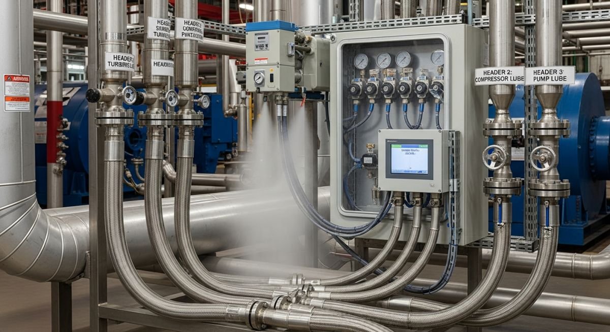
Oil Mist Lubrication System Design for Rotating Equipment Reliability
In my two decades of field experience, I have observed that bearing failure remains the leading cause of unplanned downtime in rotating equipment. Transitioning from traditional oil bath lubrication to a robust Oil Mist Lubrication System is often the single most effective upgrade for extending Mean Time Between Failures (MTBF). By maintaining a positive pressure within the bearing housing, these systems not only deliver precise lubrication but also prevent the ingress of contaminants like moisture and dust.
This guide explores the technical intricacies of designing, installing, and maintaining these systems to ensure your plant operates at peak efficiency. We will dissect the fluid dynamics, pressure requirements, and the critical role of mist distribution headers in complex piping networks.
Key Takeaways for Reliability Engineers:
- Achieve up to 40% reduction in bearing operating temperatures.
- Eliminate the need for frequent oil changes and manual sump monitoring.
- Ensure compliance with API 614 for lubrication, shaft-sealing, and control oil systems.
- Implement positive pressure sealing to block environmental contaminants.
Technical Design of an Oil Mist Lubrication System
Oil Mist Lubrication System Design: The engineering of an effective system requires precise control over air-to-oil ratios and header pressure to ensure consistent delivery across the entire piping circuit. The system operates by passing compressed, filtered air through a venturi-style generator, which atomizes the oil into particles typically ranging from 1 to 3 microns in diameter.
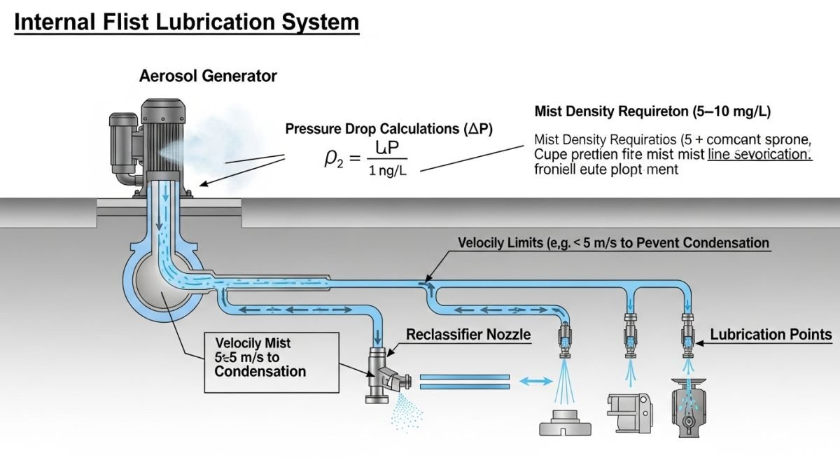
The fundamental design parameter is the maintenance of a constant header pressure, usually set between 20 and 30 inches of water column (approx. 5 to 7.5 kPa). If the pressure drops below this threshold, the mist velocity decreases, leading to premature condensation in the piping headers rather than at the bearing point. Conversely, excessive pressure can lead to oil wastage and environmental discharge issues.
Field Warning: Piping Slope Requirements
In my experience, the most common failure point in an Oil Mist Lubrication System is improper header slope. All distribution piping must be sloped back toward the oil mist generator or to designated collection drains at a minimum of 1 inch per 10 feet (1:120). Failure to maintain this slope results in “pooling,” which causes erratic mist delivery and potential bearing starvation.
When calculating the required mist volume, we utilize the bearing surface area and the number of lubrication points. The total volume flow rate (Q) is determined by the sum of the requirements for each bearing, plus a safety factor to account for piping losses. The formula for the required mist flow is Q = (N * q) * SF, where N is the number of points, q is the flow per point, and SF is the system safety factor (typically 1.2 to 1.5).
Material selection for the distribution piping is equally critical. I always specify 316L stainless steel tubing to prevent internal corrosion and particulate generation. Using carbon steel is a recipe for disaster, as internal oxidation will inevitably clog the reclassifiers—the small orifices that convert the mist back into liquid droplets at the bearing housing.
System Performance Trade-offs: Evaluating the implementation of an Oil Mist Lubrication System requires a balanced view of operational gains versus the complexity of initial infrastructure requirements.
Advantages
- Significant reduction in bearing operating temperatures due to constant oil flow.
- Positive pressure prevents ingress of moisture and abrasive particulates.
- Eliminates manual lubrication tasks, reducing human error and labor costs.
- Extends lubricant life by preventing oxidation and contamination.
- Provides a continuous, reliable supply of fresh, clean lubricant.
Disadvantages
- High initial capital expenditure for piping and generator units.
- Requires clean, dry, oil-free compressed air supply to function.
- Complex installation requiring precise slope and reclassifier sizing.
- Potential for environmental discharge if mist recovery is not managed.
- Requires specialized training for maintenance and troubleshooting.
Industrial Lubrication Deployment: The versatility of an Oil Mist Lubrication System allows for deployment across diverse high-duty environments where equipment reliability is paramount to production continuity.
Petrochemical Pump Trains
In large-scale refinery pump trains, these systems are essential for maintaining bearing integrity in high-temperature, high-vibration environments. By providing a constant flow of fresh oil, the system prevents the thermal degradation of lubricants that typically occurs in standard oil-bath setups.
Large Industrial Fan Assemblies
For forced-draft and induced-draft fans, the ingress of fly ash and dust is a constant threat to bearing life. The positive pressure maintained by the mist system acts as a dynamic seal, effectively blocking contaminants from entering the housing and causing premature wear.
Paper Mill Rollers
Paper production involves high humidity and frequent wash-down cycles that wreak havoc on traditional grease-lubricated bearings. An oil mist system ensures that the bearing surfaces remain coated in a protective oil film, significantly reducing the frequency of bearing replacements during scheduled outages.
In my two decades of field experience, I have observed that the success of an API 610 rotating equipment installation often hinges on the precise calibration of the lubrication delivery mechanism. The following table outlines the standard operating ranges for dry sump oil mist systems, which are critical for maintaining the hydrodynamic film required to prevent metal-to-metal contact in high-speed bearing housings. These values are derived from industry best practices for centrifugal pumps and electric motors operating in harsh petrochemical environments.
Engineers must ensure that the header pressure remains consistent across the entire distribution network to avoid starvation at the furthest drop points. If the pressure drops below the minimum threshold, the mist density becomes insufficient to provide the necessary cooling and lubrication, leading to premature bearing failure. Conversely, exceeding the maximum pressure can lead to excessive oil consumption and potential environmental hazards due to mist leakage from seals.
| Parameter | Typical Range | Standard Reference |
|---|---|---|
| Header Pressure | 20 to 30 inches of water column | API 614 |
| Mist Velocity | 15 to 25 feet per second | Internal Engineering Std |
| Oil Temperature | Ambient to 150 degrees Fahrenheit | ASTM D445 |
| Re-classifier Orifice | 0.020 to 0.060 inches | OEM Specification |
The complexity of an Oil Mist Lubrication System requires a rigorous understanding of the interaction between fluid dynamics, piping geometry, and mechanical seal integrity. This matrix maps the core technical entities that I frequently audit during plant reliability assessments. By standardizing these components, we ensure that the lubrication system remains compatible with the specific requirements of the rotating equipment it serves, whether it is a high-speed compressor or a standard process pump.
When reviewing these entities, focus on the material compatibility of the seals and the flow characteristics of the re-classifiers. A mismatch in these areas often results in localized oil pooling or, in worse cases, the complete loss of lubrication to the bearing race. Always verify that the piping material is compatible with the synthetic oils used in the system to prevent degradation of the internal pipe walls over time.
| Entity | Function | Standard |
|---|---|---|
| Mist Generator | Aerosolizes oil via vortex | ASME B31.3 |
| Re-classifier | Condenses mist to liquid | API 614 |
| Expansion Chamber | Reduces velocity for settling | ISO 10438 |
During my site commissioning visits, I utilize a standardized verification protocol to ensure the Oil Mist Lubrication System is installed according to the design intent. Failure to follow these steps often leads to “wet” misting, where the oil condenses too early in the piping, causing blockages and uneven distribution. Use this checklist to validate your installation before the final handover to operations.
- Slope Verification: Ensure all horizontal piping is sloped back toward the generator at a minimum of 1/2 inch per 10 feet to allow for condensate drainage.
- Re-classifier Sizing: Verify that the re-classifier orifice size matches the bearing housing volume and heat dissipation requirements per API 614.
- Leak Testing: Perform a low-pressure air test on the entire distribution header to identify potential pinhole leaks that could compromise mist density.
- Venting Check: Confirm that bearing housing vents are clear and sized correctly to prevent internal pressure buildup that would inhibit mist entry.
- Oil Quality: Verify the viscosity grade of the lubricant matches the manufacturer’s recommendation for the specific operating temperature range.
Always document the final pressure readings at the most remote drop point. If the pressure at the end of the line is significantly lower than the generator output, you must investigate the piping for internal obstructions or excessive fittings that create unnecessary pressure drops. Proper documentation is the cornerstone of long-term reliability.
Field Case Study: Real-World Application
The Problem: Chronic Bearing Failure in Centrifugal Pumps
A major refinery experienced recurring bearing failures in a bank of high-temperature pumps despite having an active lubrication system.
- Improper slope in the distribution piping caused oil pooling.
- Incorrect re-classifier selection led to insufficient mist delivery.
- High ambient temperatures caused the mist to break down prematurely.
- Lack of regular maintenance on the mist generator filters.
The Outcome: Reliability Restoration
By implementing a comprehensive redesign and maintenance program, the facility achieved significant improvements.
- Reduced bearing failure rate by 85% over 24 months.
- Increased mean time between maintenance (MTBM) by 40%.
- Optimized oil consumption by 20% through precise re-classifier tuning.
- Improved overall plant safety by eliminating oil leaks at the pump seals.
My recommendation for similar scenarios is to conduct a full audit of the piping geometry and re-classifier sizing before assuming the equipment itself is the root cause. Often, the issue is not the pump, but the delivery system’s inability to maintain the required mist quality at the point of use.
Frequently Asked Engineering Questions
How does an Oil Mist Lubrication System improve bearing life?
- It maintains a positive pressure in the bearing housing, preventing the ingress of contaminants like dust and moisture.
- The constant flow of mist provides a cooling effect, reducing the operating temperature of the bearing.
- It eliminates the risk of oil degradation associated with long-term oil bath stagnation.
- By using API 614 compliant systems, you ensure that the lubricant is always at the optimal viscosity for the load.
What is the primary cause of mist condensation in the piping?
- Piping that is not properly sloped causes oil to accumulate in low spots, creating blockages.
- Excessive use of elbows and tees creates turbulence, which forces the oil particles to coalesce prematurely.
- Ambient temperature drops can cause the oil to thicken, reducing the effectiveness of the mist.
- Using piping materials with high thermal conductivity without insulation can lead to rapid cooling of the mist.
How do I select the correct re-classifier for my equipment?
- Calculate the required oil volume based on the bearing manufacturer’s specifications.
- Ensure the re-classifier orifice size is compatible with the header pressure to maintain the desired flow rate.
- Consider the operating environment, as higher temperatures may require a different re-classifier design to prevent oil breakdown.
- Consult API 614 guidelines for standard sizing practices in industrial applications.
Can I use standard carbon steel pipe for oil mist?
- Any internal rust or mill scale will act as a nucleation point, causing the mist to condense into liquid oil.
- Stainless steel is often preferred in critical applications to prevent internal corrosion and ensure long-term cleanliness.
- Ensure all threaded connections are sealed with compatible compounds that do not introduce contaminants into the mist stream.
- Always follow ASME B31.3 for piping fabrication and cleaning standards.
What is the role of the expansion chamber in the system?
- It acts as a buffer, smoothing out pressure pulses from the mist generator.
- It helps in settling out any larger oil droplets that may have formed, ensuring only fine mist enters the distribution lines.
- It provides a convenient location for monitoring the mist quality and pressure before it enters the main header.
- Proper sizing of the expansion chamber is critical to avoid excessive pressure drops that could starve the system.
How often should I perform maintenance on the mist generator?
- Filters should be inspected monthly and replaced if there is any sign of clogging or contamination.
- The vortex generator should be cleaned periodically to ensure consistent aerosolization of the oil.
- Check the oil level and quality weekly to ensure the system is not running dry or with degraded lubricant.
- Always refer to the OEM manual for specific maintenance intervals and procedures to maintain warranty compliance.
📚 Recommended Resources: Oil Mist Lubrication System
Read these Guides
Complete Course on
Piping Engineering
Check Now
Key Features
- 125+ Hours Content
- 500+ Recorded Lectures
- 20+ Years Exp.
- Lifetime Access
Coverage
- Codes & Standards
- Layouts & Design
- Material Eng.
- Stress Analysis
