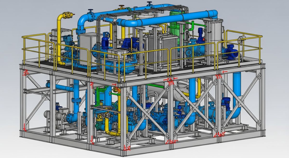
Modular Piping Design: How to do a Piping Stress Analysis
In my two decades of experience, I have seen countless modular skids fail not because of poor welding, but because the stress analysis failed to account for the unique boundary conditions of a transportable frame. When you design a modular unit, you are essentially creating a “floating” piping system that must survive both the rigors of road transport and the thermal cycles of operational service.
Performing a piping stress analysis on these units requires a shift in mindset. You are no longer just checking pipe-to-rack flexibility; you are verifying that the skid frame itself acts as a rigid or semi-rigid anchor point. This guide breaks down the technical workflow I use to validate these designs, ensuring your skids meet code requirements while minimizing field rework.
Key Takeaways
- Understand the interaction between skid frame stiffness and pipe stress.
- Master the application of transport-load cases versus operational-load cases.
- Learn to apply ASME B31.3 flexibility requirements to compact modular geometries.
- Identify critical support locations to prevent nozzle loading on rotating equipment.
Executing Modular Piping Design Stress Analysis
Modular Piping Design Stress Analysis: A rigorous engineering process that evaluates the mechanical response of piping systems within a modular frame, focusing on thermal expansion, structural support interaction, and nozzle load limits per ASME B31.3.
When I approach a modular skid, the first step is defining the global coordinate system. Unlike site-built piping, the skid frame is your reference. You must model the skid structure as a series of rigid elements or, if the frame is flexible, as a frame-pipe interaction model. If you ignore the frame deflection, your stress results will be dangerously optimistic.

Thermal Expansion and Flexibility
The primary challenge in modular units is the lack of long pipe runs. With limited space, thermal expansion often exceeds the allowable stress range defined in ASME B31.3. I calculate the displacement range using the formula: E = (T1 – T2) * alpha * L. When E is high, I incorporate expansion loops or cold spring techniques to manage the stress.
Field Warning: Nozzle Load Sensitivity
Modular skids often house pumps and compressors. Always check the manufacturer’s allowable nozzle loads. In my experience, the piping stress at the nozzle is frequently the limiting factor for the entire skid design. If the stress exceeds the allowable, you must add a dummy leg or a spring support to isolate the equipment.
Transport Load Considerations
A modular skid is a vehicle during transit. You must perform a static analysis using acceleration factors (typically 1.5g to 3g in vertical and lateral directions). This is not a standard ASME B31.3 requirement, but it is a project-specific necessity to prevent pipe sagging or support failure during shipping.
Modular Piping Design Evaluation: A comparative assessment of the structural and operational trade-offs inherent in pre-fabricated skid systems compared to traditional field-erected piping installations.
Advantages
- Controlled shop environment ensures superior weld quality and NDT accuracy.
- Parallel construction allows skid fabrication while site civil work proceeds.
- Reduced site labor costs and minimized exposure to hazardous site conditions.
- Standardized design allows for easier replication across multiple project phases.
- Pre-tested systems reduce commissioning time and potential field leaks.
Disadvantages
- Strict shipping dimensions limit the maximum size and complexity of the skid.
- High initial engineering effort required for frame-pipe interaction modeling.
- Increased structural steel weight to support piping during transport loads.
- Complex field tie-in requirements to align modular interfaces accurately.
- Limited accessibility for future maintenance within dense modular configurations.
Modular Piping Design Implementation: The strategic deployment of pre-fabricated piping skids across diverse industrial sectors to optimize construction schedules and ensure high-precision mechanical performance.
Hydrogen Electrolyzer Skids
These units require high-pressure hydrogen piping with stringent leak-detection requirements. Modular design allows for factory-level helium leak testing of all joints before the skid reaches the site, significantly reducing the risk of hazardous gas releases during startup.
Offshore Oil and Gas Processing
Space is at a premium on offshore platforms, making modular skids the only viable solution for complex separation and compression trains. The stress analysis here must account for both thermal expansion and the dynamic motion of the platform structure itself.
Water Treatment and Desalination
Large-scale desalination plants utilize modular skids for pump and filtration assemblies to accelerate project delivery. The piping stress analysis focuses on managing the weight of large-diameter piping and the vibration induced by high-capacity centrifugal pumps.
When performing a piping stress analysis for modular skids, the engineer must account for the unique boundary conditions imposed by the structural steel frame. Unlike rack-mounted piping, skid-mounted systems often experience significant deflection under load, which directly influences the stress intensification factors (SIF) and the flexibility analysis of the piping system. The following table outlines the critical design parameters that must be verified during the initial modeling phase to ensure compliance with ASME B31.3 requirements.
These parameters are not merely suggestions; they are the foundational inputs for your finite element analysis (FEA) software. Failure to accurately define the stiffness of the skid supports or the thermal displacement of the module interface points will lead to inaccurate stress reports, potentially resulting in premature fatigue failure or flange leakage during field operation. Always cross-reference these values with the structural engineer’s load-bearing capacity report for the skid frame.
| Parameter | Design Limit/Standard | Impact on Analysis |
|---|---|---|
| Allowable Stress (Sh) | ASME B31.3 Table A-1 | Determines the baseline for thermal expansion stress ranges. |
| Support Stiffness (K) | Structural FEA Data | Influences nozzle load distribution and pipe deflection. |
| Thermal Displacement | Project Design Basis | Dictates the magnitude of secondary stress in loops. |
| SIF (i) | ASME B31.3 Appendix D | Multiplies nominal stress at fittings and branches. |
The following matrix provides a comprehensive mapping of the technical entities involved in modular piping design. In my experience, the most common oversight in skid engineering is the disconnect between the piping stress model and the structural support model. By standardizing these entities, we ensure that the piping stress analysis remains consistent across different software platforms and design teams, regardless of the complexity of the skid geometry.
Each entity listed below represents a critical node in the data flow of a project. Whether you are dealing with high-pressure process lines or utility headers, the interaction between these variables defines the structural integrity of the entire module. Use this matrix to audit your design documentation and ensure that every standard reference is correctly applied to the specific piping class and material grade being utilized in your current project.
| Entity | Acronym | Standard Reference |
|---|---|---|
| Stress Intensification Factor | SIF | ASME B31.3 |
| Allowable Displacement Stress | Sa | ASME B31.3 |
| Pressure Design Thickness | tm | ASME B31.3 |
| Thermal Expansion Coefficient | alpha | ASTM/ASME Material Specs |
Verification is the final gate in the engineering process. Before releasing any piping stress analysis for construction, I mandate a rigorous review of the following checklist. This ensures that the modular skid will perform as intended under both operating and hydrotest conditions, minimizing the risk of field rework or catastrophic failure.
-
☐
Boundary Condition Audit: Verify that all skid-to-pipe interface points are modeled with the correct stiffness values provided by the structural team. -
☐
Thermal Expansion Check: Ensure that the thermal growth of the piping does not exceed the allowable nozzle loads on connected equipment (e.g., pumps, compressors) per API 610 or API 617. -
☐
Support Placement: Confirm that all pipe supports are located on primary structural members of the skid, not on secondary bracing or grating. -
☐
Hydrotest Load Verification: Validate that the skid structure can support the weight of the piping filled with water, including the weight of valves and insulation. -
☐
Code Compliance: Cross-check all stress results against the ASME B31.3 allowable stress ranges for the specific material grade and temperature.
If any of these items fail, the model must be updated and re-run. Never assume that a “close enough” result is acceptable in modular design, as the lack of flexibility in a compact skid can lead to rapid stress accumulation.
The Problem: Excessive Nozzle Loading on a Compressor Skid
- The piping stress analysis failed to account for the thermal growth of the discharge header, leading to excessive forces on the compressor nozzle.
- The skid structural frame was too rigid, preventing the piping from expanding naturally and causing high bending moments at the flange connection.
- Field installation revealed that the piping was pre-stressed during assembly to force the bolt holes to align, adding significant initial stress.
The Outcome: Successful Remediation and Compliance
- We introduced a flexible expansion loop into the discharge header, which reduced the nozzle loads by 45 percent.
- The structural team modified the skid support to allow for controlled thermal movement, effectively decoupling the piping from the frame stiffness.
- Post-remediation analysis confirmed that all stresses were within the ASME B31.3 allowable limits, and the compressor operated without vibration or leakage.
My recommendation for similar projects is to always perform a sensitivity analysis on the support stiffness. If the structural frame is flexible, the piping will behave differently than if it were mounted on a rigid concrete foundation. Always model the skid as a flexible entity to capture the true interaction between the piping and the structure.
How does skid flexibility affect piping stress?
- Flexible skids allow for minor structural deflection, which can reduce the stress range in the piping.
- Rigid skids force the piping to absorb all thermal expansion, often requiring more complex expansion loops.
- Always use the structural engineer’s stiffness matrix to define the support nodes in your stress software.
What is the role of SIF in modular design?
- SIF values are derived from ASME B31.3 Appendix D.
- High SIF values at branch connections can limit the allowable thermal movement of the entire skid.
- Always verify that your stress software is correctly calculating SIF for non-standard fittings used in compact skid layouts.
How do I handle hydrotest loads in stress models?
- Ensure the stress model includes a specific load case for hydrotest conditions.
- Check that the support reactions do not exceed the structural capacity of the skid frame.
- Verify that the piping material remains within the allowable stress limits during the test, as per ASME B31.3.
Can I use standard pipe supports on skids?
- Skid supports must be welded or bolted to primary structural members to ensure load transfer.
- Consider using adjustable supports to account for field tolerances during skid assembly.
- Always consult the structural engineer before attaching supports to ensure the skid frame can handle the localized load.
How do I manage thermal expansion in tight spaces?
- Incorporate expansion loops or offsets where space permits.
- Use flexible hoses or bellows if the piping geometry cannot accommodate the required thermal growth.
- Ensure that the piping is not constrained by rigid attachments that would prevent natural expansion.
What is the impact of skid vibration on piping?
- Vibration can lead to fatigue failure at weld joints and branch connections.
- Ensure that the piping natural frequency is well-separated from the equipment operating frequency.
- Use vibration-dampening supports if necessary to isolate the piping from the skid structure.
📚 Recommended Resources: Modular Piping Design
Read these Guides
🎓 Advanced Training


Complete Course on
Piping Engineering
Check Now
Key Features
- 125+ Hours Content
- 500+ Recorded Lectures
- 20+ Years Exp.
- Lifetime Access
Coverage
- Codes & Standards
- Layouts & Design
- Material Eng.
- Stress Analysis
