Guidelines for Large Diameter Pipe Support Design and Modeling
In my 20+ years of experience managing piping stress analysis for massive petrochemical and power generation facilities, I have seen many young engineers treat large-diameter lines just like standard 4-inch process piping. This is a recipe for structural failure. When you deal with pipe diameters of 36, 48, or 60 inches, the pipe behaves less like a classic beam and more like a thin-walled shell.
Standard beam theory assumptions in software like Caesar II can hide localized shell buckling, excessive ovalization, and high local stresses at support contact points. Designing supports for these systems requires a deep understanding of structural mechanics, local stress evaluation, and precise boundary condition modeling.
Key Engineering Takeaways
- Understand the critical transition where diameter-to-thickness (D/t) ratios exceed 100, requiring shell analysis.
- Learn how to model realistic boundary conditions in Caesar II to avoid artificial stress spikes.
- Master the application of saddle supports, wear plates, and ring girders to distribute heavy localized loads.
- Implement WRC 537 and Finite Element Analysis (FEA) to validate local stresses at support attachments.
Complete Course on
Piping Engineering
Check Now
Key Features
- 125+ Hours Content
- 500+ Recorded Lectures
- 20+ Years Exp.
- Lifetime Access
Coverage
- Codes & Standards
- Layouts & Design
- Material Eng.
- Stress Analysis
How to Master Large Diameter Pipe Support Design
When the diameter-to-thickness (D/t) ratio of a pipe exceeds 100, the pipe wall becomes highly susceptible to localized buckling and cross-sectional deformation. In my project work, I always flag any system where D/t is greater than 100 for specialized local stress checks. Standard pipe stress software assumes the pipe cross-section remains perfectly circular during bending. In reality, large-diameter thin-walled pipes ovalize under their own weight and the weight of the fluid medium.
The Mechanics of Localized Shell Stresses
To evaluate the localized stresses at support locations, we rely on the Zick analysis method for horizontal vessels and large-diameter pipes supported on saddles. The total longitudinal stress at the top and bottom of the pipe at the saddle section is calculated using the following engineering formula:
Where:
Sh = Hoop/Longitudinal Stress (psi or MPa)
P = Internal Design Pressure (psi or MPa)
R = Mean Radius of the Pipe (in or mm)
t = Corroded Wall Thickness of the Pipe (in or mm)
M = Bending Moment at the Saddle Support location (in-lb or N-mm)
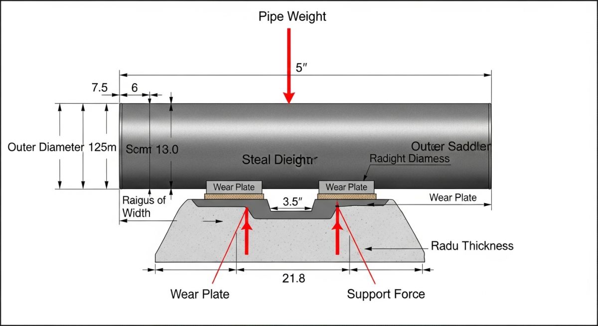
If the compressive stresses exceed the allowable buckling limit defined by ASME Section VIII Division 2, the pipe wall will buckle locally near the horn of the saddle. To prevent this, we must design a proper saddle support with an optimal contact angle (typically between 120 and 150 degrees) and integrate a wear plate.
Do not model large-diameter pipe supports as simple rigid restraints in Caesar II. A rigid restraint assumes infinite stiffness, which forces the software to calculate artificially high thermal expansion loads and moments. This often leads to over-designing structural steel or adding unnecessary expansion loops. Always calculate and input the actual radial and longitudinal stiffness of the support structure.
Modeling Boundary Conditions in Caesar II
To obtain accurate results during computer-aided modeling, I recommend using the following workflow:
- Define Support Stiffness: Instead of using “CNST” (Constant) or rigid anchors, calculate the stiffness of the structural steel support frame and input it into the Caesar II restraint spreadsheet.
- Incorporate Wear Plates: Model the wear plate as an increased local wall thickness over the length of the support to accurately capture the local section modulus.
- Evaluate Local Stresses: Extract the support reaction forces and moments from Caesar II, then import them into a local stress analysis tool like NozzlePRO or perform a manual WRC 537 / WRC 297 calculation to verify the local shell integrity.
The table below outlines the recommended maximum support spacing and minimum saddle angles for large-diameter carbon steel pipes filled with water, based on standard industrial practices and structural limits.
| Nominal Pipe Size (NPS) | Wall Thickness (in) | Max Recommended Span (ft) | Min Saddle Angle (Deg) | Wear Plate Req. |
|---|---|---|---|---|
| 30 Inch | 0.375 (Std) | 32 | 120 | Recommended |
| 36 Inch | 0.375 (Std) | 35 | 120 | Mandatory |
| 42 Inch | 0.500 (XS) | 38 | 150 | Mandatory |
| 48 Inch | 0.500 (XS) | 41 | 150 | Mandatory |
| 60 Inch | 0.625 | 45 | 150 | Mandatory (with FEA) |
Technical Mapping & Specifications Matrix
This matrix maps the core technical entities, structural parameters, and applicable design codes for large-diameter piping systems.
| Entity / Acronym | Physical Parameter | Applicable Standard | Modeling Recommendation |
|---|---|---|---|
| D/t Ratio | Diameter-to-thickness ratio | ASME B31.3 / ASME VIII-2 | If D/t > 100, perform local shell stress analysis. |
| WRC 537 | Local stress at attachments | Welding Research Council Bulletin | Use to validate local stresses on the pipe wall. |
| Saddle Support | 120 to 150-degree cradle | Zick Analysis Method | Model with realistic radial stiffness values. |
| Ring Girder | Full 360-degree reinforcement | AWWA M11 / ASME VIII-2 | Required for high-load anchor locations. |
Field Checklist for Large Diameter Pipe Support Design
Before releasing a large-diameter piping design for fabrication, I always run through a strict verification checklist. This ensures that the theoretical model matches the physical reality of the construction site.
Engineering Validation Checklist
-
Verify D/t Ratio Limits: Ensure that any pipe with a D/t ratio exceeding 100 has been flagged for local shell stress evaluation using WRC 537 or FEA.
-
Saddle Contact Angle: Confirm that all saddle supports have a minimum contact angle of 120 degrees to distribute the weight load effectively.
-
Wear Plate Dimensions: Check that wear plates extend at least 1.0 inch (25mm) beyond the saddle horns in both longitudinal and circumferential directions.
-
Weep Hole Integration: Ensure all wear plates have a 1/4-inch NPT weep hole at the lowest point to prevent moisture entrapment and localized corrosion.
-
Support Stiffness Input: Verify that the structural steel stiffness has been calculated and input into the Caesar II model instead of using rigid boundary conditions.
-
Thermal Movement Clearance: Confirm that sliding supports have sufficient clearance on the structural steel beams to accommodate the calculated thermal displacements.
Field Case Study: Real-World Application
The Problem: Localized Buckling on a 48-Inch Cooling Water Line
During the commissioning phase of a combined-cycle power plant, a 48-inch cooling water line (wall thickness of 0.375 inches, D/t ratio of 128) developed visible localized buckling directly above a standard shoe support. The original design team had modeled the support as a simple rigid point restraint in Caesar II, neglecting the localized shell stresses. Under the combined weight of the water and thermal expansion, the pipe wall deformed, leading to a high risk of catastrophic structural failure.
The Outcome: Redesign and FEA Validation
My team was brought in to resolve the issue. We immediately remodeled the piping system using Finite Element Analysis (FEA) to capture the true shell behavior. We replaced the standard shoe support with a 120-degree saddle support equipped with a 10mm thick wear plate. This modification distributed the radial load over a much larger surface area, reducing the localized shell stress from 45,000 psi (which exceeded the yield strength) to a safe 12,500 psi, well within the allowable limits of ASME Section VIII Division 2.
This field experience highlights why we must never rely solely on beam-element software for thin-walled, large-diameter systems. Always perform a local stress check when the D/t ratio exceeds the threshold of 100.
Frequently Asked Engineering Questions
What is the critical D/t ratio where standard beam modeling fails?
How do you model a saddle support in Caesar II?
Why are wear plates required for large diameter pipe supports?
How does the Zick analysis method apply to piping supports?
What are the consequences of over-constraining a large pipeline?
When should Finite Element Analysis (FEA) be used instead of WRC 107/297?
===FAQ_BLOCK===
Complete Course on
Piping Engineering
Check Now
Key Features
- 125+ Hours Content
- 500+ Recorded Lectures
- 20+ Years Exp.
- Lifetime Access
Coverage
- Codes & Standards
- Layouts & Design
- Material Eng.
- Stress Analysis