Table of Contents
Why Insulated Pipe Supports Are Required for Industrial Piping
In my 20-plus years of piping engineering, I have seen millions of dollars in energy losses and catastrophic structural failures trace back to a single, overlooked detail: the pipe support. Many engineers spend weeks optimizing insulation thickness along the run of a pipe, only to clamp a bare steel shoe directly to a cold or hot line. This creates a massive thermal highway—a thermal bridge—that destroys system efficiency.
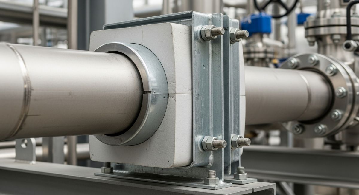
That is where insulated pipe supports come into play. These are not just standard clamps; they are highly engineered assemblies designed to carry the physical weight of the piping system while maintaining a continuous thermal barrier. Whether you are dealing with superheated steam at 500 degrees Celsius or cryogenic LNG at minus 162 degrees Celsius, selecting the correct support is a fundamental requirement for safe, efficient plant operation.
Key Engineering Takeaways
- Thermal Isolation: Eliminates the direct conductive heat path between the process fluid and structural steel.
- Condensation Control: Prevents moisture and ice formation on cold and cryogenic piping systems.
- Load Distribution: High-density inserts transfer heavy piping loads without crushing the insulation material.
- System Longevity: Minimizes the risk of corrosion under insulation (CUI) by maintaining vapor barrier integrity.
How Do Insulated Pipe Supports Prevent Thermal Bridging?
To understand why insulated pipe supports are so critical, we must look at the physics of heat transfer. In a standard uninsulated support, a steel shoe is welded or clamped directly to the pipe. Steel has a high thermal conductivity (approximately 50 W/m·K). This direct contact allows heat to flow rapidly out of a hot pipe (or into a cold pipe), bypassing the surrounding thermal insulation.
We calculate the localized heat loss (q) at an uninsulated support point using a modified Fourier’s Law of heat conduction:
Where:
• q = Heat loss rate (Watts)
• k = Thermal conductivity of the material (W/m·K)
• L = Equivalent length of the thermal bridge (m)
• Ti = Internal process temperature (K)
• To = Ambient temperature (K)
• ro / ri = Ratio of outer to inner radius of the insulation system
By replacing the direct steel-to-steel contact with a high-density, low-conductivity insert (such as cellular glass or polyurethane foam with a k-value of 0.03 to 0.08 W/m·K), we reduce the heat transfer rate at the support point by up to 95 percent.
Compressive Strength and Structural Integrity
The primary engineering challenge with insulated supports is balancing thermal resistance with mechanical strength. Standard insulation materials like mineral wool are excellent thermal barriers but have virtually zero compressive strength. If you place a heavy pipe on mineral wool, it will crush instantly, leading to piping misalignment and structural failure.
Insulated supports solve this by utilizing high-density, load-bearing materials. The compressive stress (S) on the support insert is calculated as:
Where F is the total vertical load (including pipe weight, fluid weight, and dynamic forces) and A is the contact area of the load-bearing insert. The calculated stress must always be lower than the allowable compressive strength of the material, incorporating a safety factor of at least 3.0 in accordance with ASME B31.3 design guidelines.
Selecting the correct insert material is the most critical decision in the design of insulated pipe supports. The table below outlines the physical properties of the most common load-bearing insulation materials used in modern industrial plants.
| Material Type | Temp Range (°C) | Compressive Strength (MPa) | Thermal Conductivity (W/m·K) | Primary Application |
|---|---|---|---|---|
| Calcium Silicate | Ambient to 650 | 1.0 to 2.5 | 0.06 to 0.09 | High-temperature steam, hot process lines |
| Cellular Glass | -268 to 430 | 0.6 to 1.6 | 0.04 to 0.06 | Cryogenic, dual-temperature, and chemical lines |
| Polyurethane Foam (PUF) | -200 to 120 | 1.5 to 4.5 | 0.03 to 0.05 | Cold water, chilled systems, low-temp hydrocarbons |
| Densified Wood Laminate | -200 to 100 | 40.0 to 90.0 | 0.15 to 0.20 | Heavy load cryogenic anchors and guides |
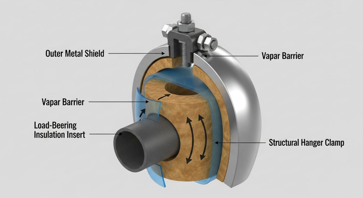
This matrix maps the individual components of an insulated support assembly to their primary functions, material options, and governing industry standards.
| Component | Primary Function | Material Options | Standard Reference |
|---|---|---|---|
| Load-Bearing Insert | Carries pipe weight, blocks heat transfer | Cellular Glass, Calcium Silicate, PUF | ASTM C585, ASTM C533 |
| Outer Metallic Shield | Distributes clamping load, protects insert | Galvanized Steel, Stainless Steel 304/316 | MSS SP-58, ASTM A240 |
| Vapor Barrier Jacket | Prevents moisture ingress in cold systems | Elastomeric membranes, Mylar, Aluminum foil | ASTM C1136 |
| Structural Shoe / Clamp | Connects assembly to structural steel | Carbon Steel (hot-dip galvanized), Alloy Steel | ASME B31.3, MSS SP-69 |
Installing Insulated Pipe Supports Correctly on Site
Even the best-engineered support will fail if installed incorrectly. In my field audits, I frequently find supports installed backward, vapor barriers punctured by careless handling, or clamps over-torqued to the point of crushing the load-bearing insert. Use this checklist on-site to ensure your installations meet the highest engineering standards.
Field Inspection Checkpoints
-
Material Verification: Confirm that the insert material matches the piping operating temperature specified in the isometric drawings (e.g., Cellular Glass for cryogenic, Calcium Silicate for high-temp steam). -
Vapor Barrier Integrity: For cold and cryogenic lines, inspect 100 percent of the vapor barrier jacket. Any puncture, tear, or unsealed joint must be repaired immediately using approved vapor-barrier mastic or tape. -
Shield Centering: Ensure the outer metallic shield is perfectly centered over the load-bearing insert. Misalignment causes localized stress concentrations on the edges of the insert. -
Clamp Torque Control: Verify that the structural clamp bolts are tightened using a calibrated torque wrench to the manufacturer’s specified torque values. Do not over-tighten. -
Thermal Expansion Clearance: Confirm that the support shoe has sufficient clearance on the structural steel beam to slide freely during thermal expansion cycles without falling off the beam.
Field Case Study: Real-World Application
My direct recommendation for any cryogenic or high-temperature project is to mandate pre-fabricated, factory-sealed insulated pipe supports. Field-fabricated supports rarely achieve the vapor-tight seal or precise dimensional tolerances required to prevent long-term thermal bridging and structural degradation.
Frequently Asked Engineering Questions
What is the primary purpose of an insulated pipe support?
Which materials are commonly used for load-bearing inserts?
How do insulated pipe supports prevent corrosion under insulation (CUI)?
What standards govern the design of insulated pipe supports?
Can I use standard insulation inside a pipe clamp?
How does thermal expansion affect insulated pipe supports?
Complete Course on
Piping Engineering
Check Now
Key Features
- 125+ Hours Content
- 500+ Recorded Lectures
- 20+ Years Exp.
- Lifetime Access
Coverage
- Codes & Standards
- Layouts & Design
- Material Eng.
- Stress Analysis

📚 Recommended Resources: insulated pipe supports
Read these Guides
🎥 Watch Tutorials

Related posts:
![Comparison of high viscosity honey and low viscosity water pouring to demonstrate fluid resistance]()
Understanding Newton's Law of Viscosity and Key Fluid Flow Factors
![A puddle flange installed on a PVC pipe embedded in a concrete wall cross-section]()
What is a Puddle Flange? Types, Applications, and Key Advantages
![Chemical injection system administering corrosion inhibitors to a steel pipeline in an oil and gas facility.]()
Comprehensive Guide to Corrosion Inhibitors in the Oil and Gas Industry
![A metallic two-hole pipe strap securing a copper pipe to a wooden wall beam.]()
What is a Pipe Strap? Its Types, Importance, Materials, Applications
![Heavy-duty vertical pipe support riser clamps installed on steel piping through concrete floors.]()
How to Design and Install Vertical Pipe Support Systems
![Industrial piping system suspended from a ceiling using various types of pipe hanger supports.]()
How to Select and Design Pipe Hanger Supports for Industrial Piping