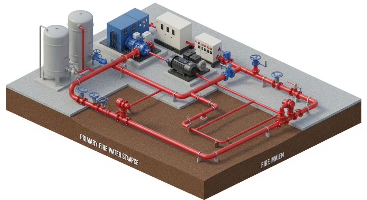
Introduction to Fire Protection System Design and Engineering Standards
In my two decades of experience managing complex piping projects, I have learned that a robust Fire Protection System is not merely a regulatory requirement; it is the final line of defense for your facility. Whether you are designing a high-pressure deluge system for a petrochemical plant or a standard wet-pipe sprinkler network for a warehouse, the engineering principles remain constant: reliability, hydraulic efficiency, and strict adherence to international codes.
This guide explores the technical nuances of fire fighting system design, focusing on the critical interplay between fluid dynamics and safety standards. We will dissect how to calculate friction losses, select appropriate pipe materials, and ensure that your fire water loop remains pressurized and ready for immediate deployment during an emergency.
Key Takeaways for Engineers
- Mastering NFPA 13, 14, and 20 for system compliance.
- Understanding the Hazen-Williams equation for hydraulic demand calculations.
- Selecting piping materials based on corrosion resistance and pressure ratings.
- Implementing redundant water supply loops to prevent single-point failures.
Technical Fundamentals of Fire Protection System Design
Fire Protection System Hydraulics: The systematic application of fluid mechanics to ensure adequate flow and pressure at the most remote sprinkler head or hydrant, strictly adhering to NFPA 13 and NFPA 20 design criteria.
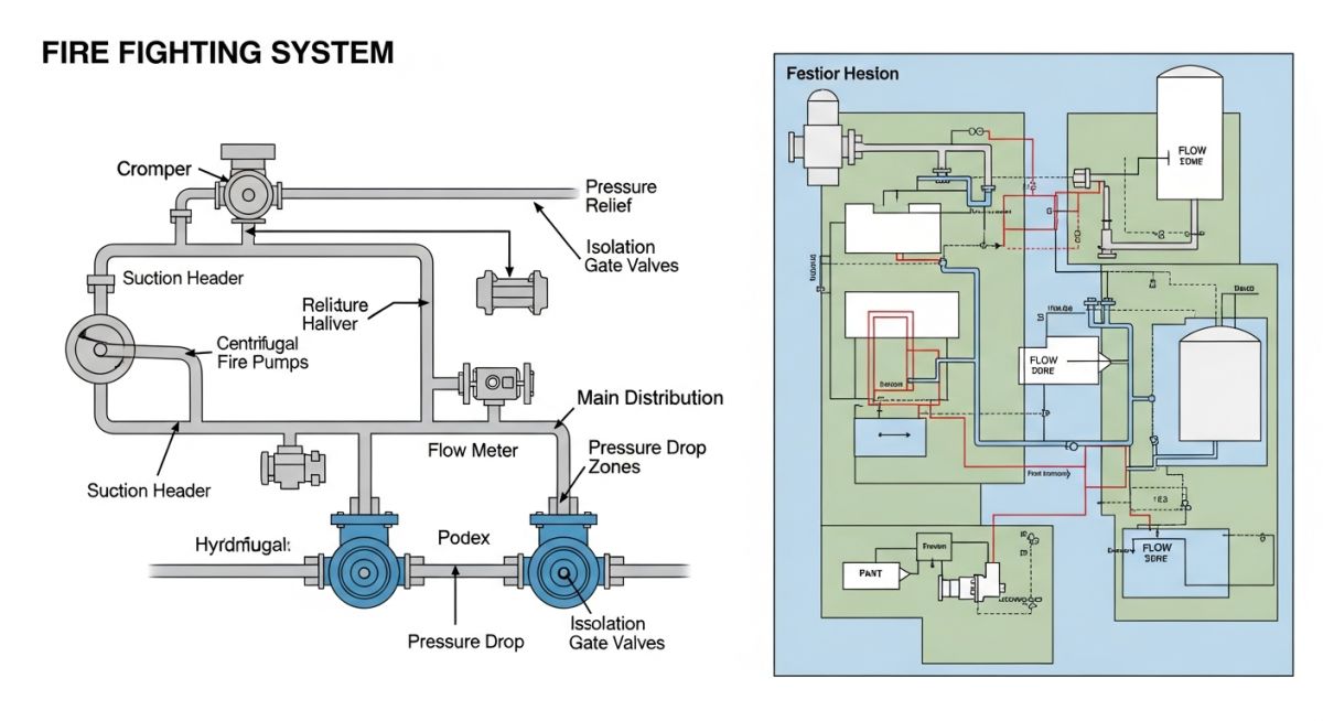
Designing a Fire Protection System requires a deep dive into hydraulic demand. I always start by defining the “Design Area” based on the hazard classification of the facility. For light hazard occupancies, the demand is significantly lower than for high-piled storage or flammable liquid processing areas. The primary tool for our calculations is the Hazen-Williams formula, which relates the pressure drop to the flow rate, pipe diameter, and the C-factor (roughness coefficient).
When calculating friction loss, I use the following expression: P = 4.52 * Q^1.85 / (C^1.85 * d^4.87). In this equation, P represents the pressure drop in psi per foot, Q is the flow in gallons per minute, C is the pipe roughness, and d is the internal pipe diameter in inches. It is vital to account for equivalent lengths of fittings and valves, as these often contribute more to the total pressure drop than the straight pipe runs themselves.
Field Warning: Velocity Limitations
Never allow water velocity in fire mains to exceed 20 feet per second (fps) to prevent water hammer and pipe erosion. In my experience, keeping velocities between 8 and 12 fps provides the best balance between pipe sizing economy and system longevity.
Material selection is equally critical. For underground fire mains, I typically specify ductile iron pipe with cement mortar lining to prevent internal corrosion. Above-ground piping often utilizes Schedule 40 black steel, though in corrosive environments, I have successfully implemented galvanized or stainless steel piping to meet the stringent requirements of ASME B31.3 for process piping integration.
Finally, the fire pump selection must be based on the “Pump Curve.” The pump must be capable of providing the required flow at the required pressure, with a safety margin of at least 10% to account for future system degradation or potential pipe scaling. Always ensure your pump room layout allows for adequate suction piping straight runs to prevent cavitation, which is the leading cause of premature pump failure in industrial settings.
Fire Protection System Performance: A comparative analysis of active suppression technologies, evaluating the operational benefits of reliability against the inherent challenges of maintenance and capital expenditure.
Advantages
- Immediate automated response to thermal triggers.
- Significant reduction in insurance premiums for industrial sites.
- Proven track record in preventing catastrophic structural collapse.
- Scalable design allows for future facility expansion.
- Integration with building management systems for real-time monitoring.
Disadvantages
- High initial capital expenditure for pumps and tanks.
- Requires rigorous, recurring inspection and testing schedules.
- Risk of accidental discharge causing water damage to equipment.
- Complex hydraulic balancing required for large-scale networks.
- Corrosion potential in stagnant wet-pipe systems over time.
Industrial Fire Protection Deployment: The strategic implementation of specialized suppression systems across diverse sectors, tailored to specific hazard profiles and environmental conditions.
Petrochemical Processing Facilities
These environments require high-capacity deluge systems and foam-water monitors to combat flammable liquid fires. The design must account for extreme ambient temperatures and the potential for rapid fire spread, necessitating redundant fire water loops and high-pressure pumping stations.
Automated High-Piled Storage Warehouses
In these facilities, in-rack sprinkler systems are essential to ensure water reaches the base of the fire through dense inventory. We utilize hydraulic modeling to ensure that the density and area of coverage meet the specific commodity classification defined by NFPA 13.
Data Center and Server Rooms
Traditional water-based systems are often replaced by clean agent gas suppression systems to protect sensitive electronic equipment. These systems must be designed with room integrity testing to ensure the concentration of the extinguishing agent is maintained for the required soak time.
Designing a robust Fire Protection System requires strict adherence to hydraulic pressure limits and flow velocity constraints to prevent pipe erosion and water hammer damage. In my experience, the selection of pipe material—typically Schedule 40 black steel for wet systems—must be balanced against the friction loss coefficients defined by the Hazen-Williams formula. Engineers must ensure that the residual pressure at the most hydraulically remote sprinkler head meets the minimum discharge requirements specified by NFPA 13.
The following table outlines the critical design thresholds I utilize during the preliminary hydraulic modeling phase. These values ensure that the system remains within the operational envelope of standard fire pumps and piping components, preventing cavitation at the pump suction and excessive pressure drops across the distribution manifold.
| Parameter | Standard/Limit | Engineering Note |
|---|---|---|
| Max Velocity (Steel) | 20 ft/s | Prevents erosion and noise |
| Min Residual Pressure | 7 psi | Per NFPA 13 requirements |
| Hazen-Williams C-Factor | 120 | Standard for new black steel |
The integration of various components within a Fire Fighting System necessitates a clear understanding of the relationship between mechanical hardware and regulatory standards. Each entity, from the fire pump controller to the individual sprinkler head, must be mapped against its respective NFPA code to ensure system-wide compliance and interoperability during an emergency event.
This matrix serves as a quick-reference guide for piping engineers to identify the governing standards for specific system elements. By maintaining this alignment, we ensure that the design documentation remains audit-ready and that the procurement phase aligns with the technical specifications established during the front-end engineering design (FEED) stage.
Verification of a Fire Protection System installation is a critical phase that demands meticulous attention to detail. Before commissioning, I always perform a comprehensive site walk-through to ensure that the physical installation matches the approved hydraulic calculations and piping isometric drawings. Discrepancies at this stage can lead to catastrophic failure during a fire event, making this checklist an essential tool for quality assurance.
- ☐ Pipe Support Integrity: Verify that all seismic bracing and hangers comply with NFPA 13 spacing requirements.
- ☐ Valve Accessibility: Ensure all control valves are locked in the open position and are clearly labeled with permanent signage.
- ☐ Hydrostatic Testing: Confirm that the piping network has been tested at 200 psi for two hours without pressure loss.
- ☐ Clearance Zones: Check that no storage or equipment obstructs the spray pattern of any installed sprinkler heads.
- ☐ Pump Room Ventilation: Validate that the fire pump room meets ambient temperature requirements for diesel engine reliability.
Each item on this list must be signed off by the lead piping engineer and the fire safety officer. If any item fails, the system must be isolated and remediated before proceeding to the final acceptance test. Documentation of these checks is mandatory for insurance compliance and local fire marshal approval.
Problem: Unexpected Pressure Drop During Commissioning
- Significant pressure loss detected at the most remote branch line.
- Internal pipe debris identified as a result of poor flushing procedures.
- Incorrect orifice sizing in the test header causing flow imbalance.
- Lack of proper air release valves leading to air pockets in high-elevation piping.
Outcome: System Optimization and Successful Certification
- Implemented a rigorous multi-stage flushing protocol for all distribution lines.
- Recalibrated the hydraulic model to account for actual field-measured friction losses.
- Installed high-capacity automatic air release valves at all system high points.
- Achieved full NFPA compliance and received final fire marshal sign-off within 48 hours.
My recommendation for similar projects is to prioritize the cleanliness of the piping network during the construction phase. Even minor mill scale or construction debris can significantly alter the C-factor of the pipe, rendering your initial hydraulic calculations inaccurate. Always perform a thorough flush before installing the final sprinkler heads to ensure the system performs exactly as designed.
Frequently Asked Engineering Questions
How do I determine the correct pipe size for a fire fighting system?
- Calculate the total flow rate required based on the hazard classification per NFPA 13.
- Use the Hazen-Williams formula to determine friction loss for various pipe diameters.
- Ensure the velocity does not exceed 20 feet per second to prevent pipe degradation.
- Verify that the residual pressure at the most remote head meets the minimum required by the specific sprinkler listing.
What is the difference between wet and dry pipe systems?
- Wet pipe systems are filled with pressurized water, allowing for immediate discharge upon sprinkler activation.
- Dry pipe systems are filled with pressurized air or nitrogen, which must be expelled before water can reach the sprinkler head.
- Dry systems are specifically designed for environments subject to freezing temperatures where water would otherwise damage the piping.
- Maintenance for dry systems is more complex due to the need for air compressors and specialized dry pipe valves.
Why is the C-factor important in hydraulic calculations?
- A higher C-factor indicates a smoother pipe, resulting in lower friction loss and higher flow efficiency.
- As pipes age, corrosion and tuberculation reduce the C-factor, increasing the pressure drop over time.
- Engineers must use conservative C-factor values to ensure the system remains effective throughout its entire service life.
- Standard values are provided in NFPA 13 for different pipe materials like black steel, galvanized steel, and plastic.
How often should fire protection systems be inspected?
- Weekly or monthly inspections are required for gauges and control valves to ensure they are in the correct position.
- Annual inspections cover the entire system, including sprinkler heads, piping, and alarm devices.
- Five-year internal pipe inspections are necessary to check for internal obstructions or corrosion buildup.
- All inspection results must be documented in a logbook and kept on-site for review by the local authority having jurisdiction.
What is the role of a fire pump in the system?
- It boosts the system pressure to ensure that the most remote sprinkler head receives adequate water volume.
- Pumps must be installed in accordance with NFPA 20, which covers pump selection, installation, and testing.
- The pump controller must be capable of starting the pump automatically upon a drop in system pressure.
- Redundancy is often required, meaning a secondary pump or a backup power source is necessary for high-risk industrial facilities.
Can I use plastic piping in a fire protection system?
- CPVC is the most common plastic used, provided it is specifically rated for fire sprinkler applications.
- Plastic piping is restricted in certain high-hazard areas or where it may be exposed to extreme heat or mechanical damage.
- Installation must strictly follow the manufacturer’s instructions regarding support spacing and solvent welding techniques.
- Always verify local building codes, as some jurisdictions prohibit plastic piping in specific types of commercial or industrial structures.
📚 Recommended Resources: Fire Protection System
Read these Guides
🎓 Advanced Training



Complete Course on
Piping Engineering
Check Now
Key Features
- 125+ Hours Content
- 500+ Recorded Lectures
- 20+ Years Exp.
- Lifetime Access
Coverage
- Codes & Standards
- Layouts & Design
- Material Eng.
- Stress Analysis
