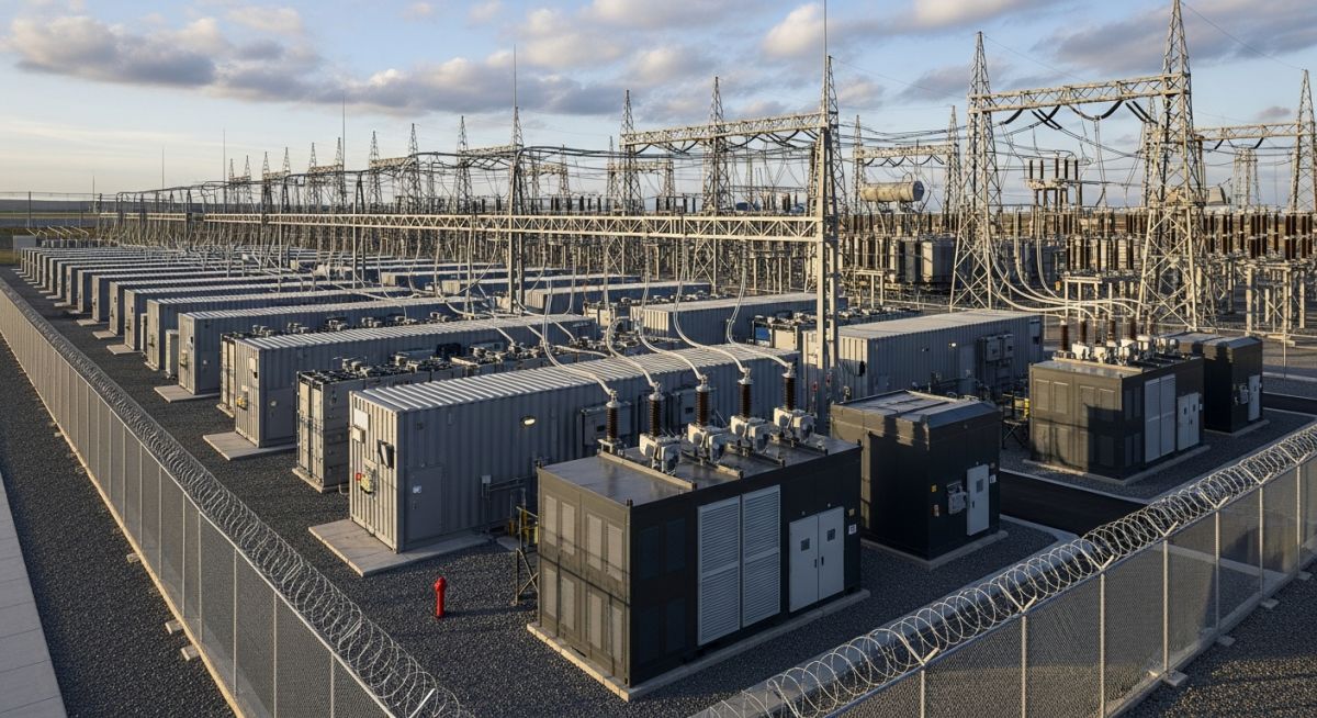
Grid Applications of Battery Energy Storage Systems: A Technical Overview
In my two decades of experience navigating complex infrastructure projects, I have observed that the transition toward renewable energy sources necessitates a fundamental shift in how we manage grid stability. Battery Energy Storage Systems (BESS) have emerged as the primary technical solution to address the inherent intermittency of solar and wind power. By providing rapid-response power injection and absorption, these systems act as the “shock absorbers” of the modern electrical grid.
This article explores the engineering mechanics behind BESS, focusing on how these systems facilitate frequency regulation, peak shaving, and black start capabilities. We will examine the technical requirements for grid interconnection and the operational parameters that define successful energy storage deployment in high-voltage environments.
Key Takeaways for Engineers:
- Understanding the sub-second response capabilities of BESS for frequency regulation.
- Optimizing power-to-energy ratios for specific grid-scale applications.
- Navigating the regulatory and safety standards for large-scale lithium-ion installations.
- Evaluating the impact of BESS on reducing thermal plant cycling and wear.
Technical Mechanics of Grid Applications of Battery Energy Storage Systems
BESS Grid Integration: The application of battery energy storage systems involves complex power electronics and control algorithms designed to maintain grid frequency and voltage within strict NERC reliability standards.
At the heart of any grid-scale BESS is the Power Conversion System (PCS), which acts as the interface between the DC battery racks and the AC grid. The PCS must handle bidirectional power flow, allowing the system to charge during periods of excess generation and discharge during peak demand. From an engineering perspective, the primary challenge lies in the control loop latency; for frequency regulation, the system must detect a frequency deviation and initiate a power response within milliseconds.
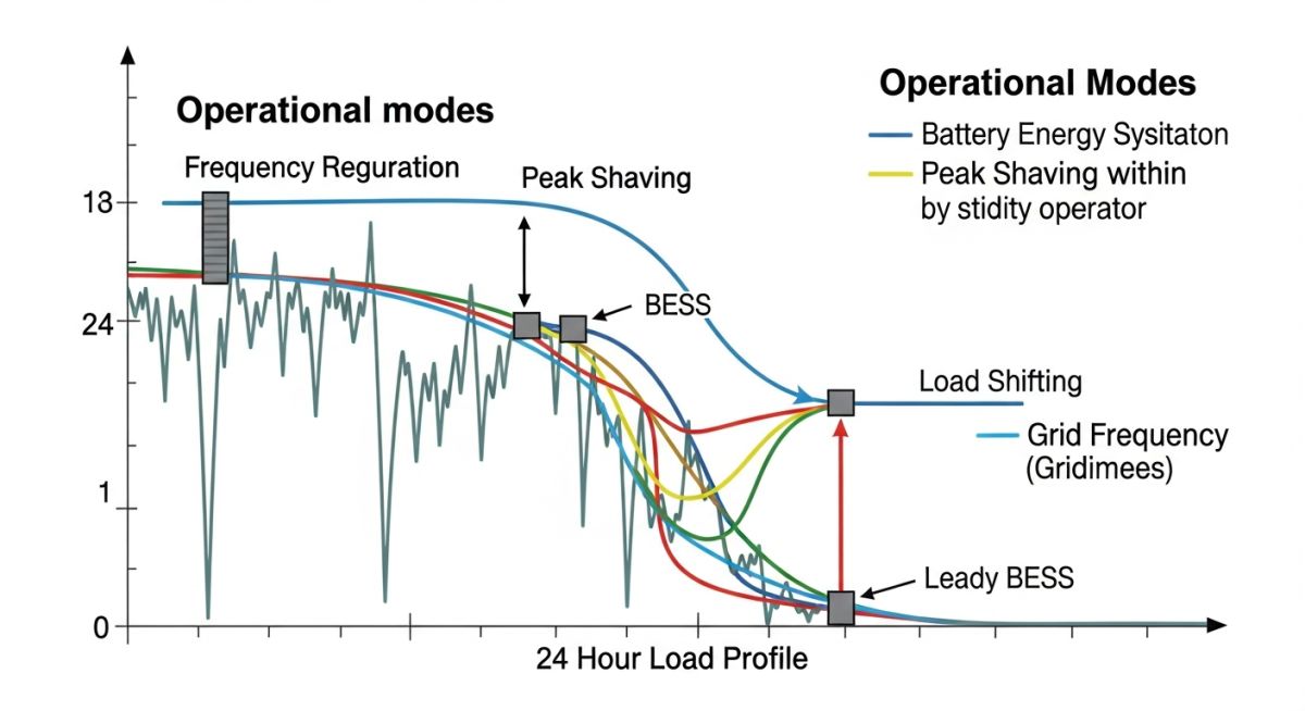
When calculating the required capacity for peak shaving, we utilize the load duration curve of the specific substation. The objective is to identify the “peak” portion of the load that exceeds the transformer’s thermal rating or the economic threshold of the utility. The calculation follows the formula: Required Power (kW) = Peak Load – Threshold Limit. The energy capacity (kWh) is then determined by the duration of the peak event, typically ranging from 2 to 4 hours.
Engineering Limitation Warning:
Thermal management is the most critical constraint in BESS design. As the battery modules discharge, internal resistance leads to heat generation. If the cooling system fails to maintain the electrolyte temperature within the manufacturer’s specified range, the system will trigger a derating event, significantly reducing the available power output and potentially causing permanent degradation of the cell chemistry.
Voltage support is achieved through reactive power (VAR) compensation. Unlike traditional capacitor banks, a BESS can provide both inductive and capacitive reactive power by adjusting the phase angle of the inverter output. This allows the grid operator to maintain voltage profiles at the point of common coupling (PCC) even when the active power flow is minimal. This capability is governed by the IEC 61850 communication protocol, which ensures seamless integration with existing SCADA systems.
BESS Operational Trade-offs: The implementation of battery energy storage systems requires a balanced evaluation of high-speed grid response benefits against the physical limitations of electrochemical storage degradation.
Advantages
- Sub-second response time for frequency regulation services.
- Modular scalability allowing for incremental capacity expansion.
- Zero emissions during operation, supporting decarbonization goals.
- Ability to provide synthetic inertia to grids with high inverter-based generation.
- Reduced mechanical stress on conventional thermal power plants.
Disadvantages
- Finite cycle life leading to capacity fade over time.
- High initial capital expenditure for lithium-ion technology.
- Complex thermal management requirements to prevent thermal runaway.
- Dependency on rare earth materials for battery manufacturing.
- Potential for fire safety risks requiring specialized suppression systems.
Grid-Scale BESS Deployment: The practical application of battery energy storage systems spans from transmission-level frequency control to localized distribution-level voltage optimization and peak demand management.
Transmission Frequency Regulation
BESS units are deployed at major substations to provide fast frequency response (FFR) by injecting or absorbing active power within milliseconds of a frequency deviation. This service is essential for maintaining the 50/60 Hz grid stability in systems with high penetration of non-synchronous renewable energy sources.
Distribution Peak Shaving
Utilities utilize BESS to mitigate localized peak demand on distribution feeders, effectively deferring the need for costly infrastructure upgrades like transformer replacements. By discharging during peak hours, the system keeps the feeder load below the thermal limit of the existing conductors and switchgear.
Black Start Capability
In the event of a total grid collapse, BESS provides the necessary cranking power to restart auxiliary systems in large power plants. Unlike diesel generators, BESS offers an instantaneous, high-current start-up capability that is critical for restoring power to the grid in a controlled and reliable manner.
When evaluating Battery Energy Storage Systems for grid-scale integration, engineers must prioritize specific performance metrics that dictate the system’s ability to respond to transient grid events. These parameters are not merely theoretical; they define the operational envelope for IEEE 1547 compliance and ensure that the BESS can provide reliable ancillary services without premature degradation of the electrochemical cells.
The following table outlines the critical performance thresholds required for various grid applications. Note that response times are measured in milliseconds for frequency regulation, whereas energy capacity requirements for peak shaving are measured in hours. Understanding these trade-offs is fundamental for sizing the power conversion system (PCS) and the battery management system (BMS) architecture effectively.
| Application | Response Time | Discharge Duration | Cycle Frequency |
|---|---|---|---|
| Frequency Regulation | Less than 200ms | Seconds to Minutes | Very High |
| Voltage Support | Less than 500ms | Minutes | Moderate |
| Peak Shaving | Seconds | 2 to 6 Hours | Low |
| Black Start | Seconds | 1 to 4 Hours | Very Low |
Engineers should utilize these data points to perform sensitivity analyses on the state-of-health (SoH) of the battery modules. High-cycle applications like frequency regulation necessitate lithium-titanate or specialized lithium-iron-phosphate chemistries, whereas energy-dense applications like peak shaving may allow for more cost-effective, lower-cycle-life chemistries.
The integration of BESS into modern power grids requires a sophisticated mapping of electrical components to their respective grid-stabilization functions. This matrix serves as a technical reference for identifying which hardware components are responsible for specific grid-side outcomes, ensuring that system design aligns with NERC reliability standards.
By cross-referencing the physical assets with their operational roles, project managers can better allocate capital expenditure (CAPEX) and operational expenditure (OPEX) during the procurement phase. This matrix highlights the synergy between the power conversion system, the battery management system, and the grid-interface transformers.
| Component | Primary Function | Standard Reference |
|---|---|---|
| PCS (Inverter) | Active/Reactive Power Control | UL 1741 |
| BMS (Controller) | Cell Balancing & Safety | IEC 62619 |
| Grid Transformer | Voltage Step-up/Isolation | IEEE C57 |
| SCADA Interface | Grid Dispatch Coordination | IEC 61850 |
Adherence to these standards is non-negotiable for grid-connected assets. Failure to verify the compatibility of the SCADA interface with existing utility protocols often leads to significant commissioning delays and potential non-compliance penalties during grid-code testing.
Before energizing any grid-scale battery energy storage system, a comprehensive site verification process is mandatory. In my experience, the most common points of failure during commissioning are not the battery cells themselves, but the communication latency between the BESS controller and the utility’s energy management system (EMS). This checklist ensures that all physical and digital interfaces meet the rigorous demands of modern grid operations.
-
Grounding Integrity: Verify that the grounding grid resistance meets IEEE 80 requirements for fault current dissipation. -
Communication Latency: Confirm that the round-trip time for dispatch signals is below 50ms to satisfy frequency regulation requirements. -
Thermal Management: Validate that the HVAC system maintains cell temperatures within the manufacturer’s specified range under full-load discharge. -
Protection Coordination: Ensure that the relay settings for the BESS interface transformer are coordinated with the utility’s upstream protection devices. -
Black Start Logic: Test the islanding transition sequence to ensure the BESS can establish a stable voltage reference without grid power.
Each of these checkpoints must be documented in the site commissioning report. Pay particular attention to the protection coordination study; if the BESS is intended to provide black start capability, the relay settings must be dynamic to account for the lack of a stiff grid during the initial energization phase. Always perform a secondary verification of the firmware versions across all power conversion modules to prevent synchronization errors during parallel operation.
The Challenge: Grid Instability in a High-Renewable Microgrid
A remote industrial facility faced frequent voltage fluctuations and frequency instability due to the high penetration of intermittent solar PV generation.
- Rapid voltage swings caused by cloud cover transients.
- Inability of existing diesel generators to respond to sub-second frequency deviations.
- High operational costs due to excessive spinning reserve requirements.
- Frequent tripping of sensitive manufacturing equipment during grid disturbances.
The Outcome: Successful BESS Integration
The installation of a 5MW/10MWh BESS provided the necessary inertia and fast-acting power injection to stabilize the local grid.
- Achieved 99.9% uptime for frequency regulation services.
- Reduced diesel fuel consumption by 22% through optimized load shifting.
- Eliminated equipment trips by maintaining voltage within a 2% tolerance band.
- Successfully demonstrated black start capability during a simulated grid outage.
The recommendation for similar projects is to prioritize the integration of the BESS controller with the site’s existing SCADA system early in the design phase. By utilizing predictive algorithms for solar forecasting, the BESS can proactively adjust its state-of-charge to prepare for anticipated generation drops, thereby maximizing the system’s overall grid-stabilization impact.
How does BESS provide frequency regulation?
- The response is near-instantaneous, often faster than traditional mechanical governors.
- This rapid response helps maintain the balance between generation and load.
- It reduces the need for traditional power plants to operate in a part-load state.
What is the role of BESS in black start?
- The BESS provides the initial surge current required to energize transformers.
- It maintains a stable voltage reference until other generation sources can synchronize.
- This capability is vital for restoring power after a total grid collapse.
How does peak shaving reduce utility costs?
- It flattens the load profile, preventing the facility from hitting expensive peak thresholds.
- The BESS is recharged during off-peak hours when electricity prices are lower.
- This strategy optimizes the total cost of energy over the billing cycle.
What standards govern BESS grid interconnection?
- IEEE 1547 ensures safe and reliable interconnection with the utility grid.
- UL 1741 covers the performance of inverters and controllers.
- Compliance with these standards is required for utility approval and grid code adherence.
How does BESS provide voltage support?
- Injecting reactive power helps raise the local grid voltage.
- Absorbing reactive power helps lower the local grid voltage.
- This dynamic control is essential for maintaining voltage stability in distribution networks.
What is the impact of BESS on grid stability?
- It mitigates the impact of intermittent renewable energy sources.
- It provides a buffer against sudden load changes or generation losses.
- It improves the overall resilience of the power system against outages.
Complete Course on
Piping Engineering
Check Now
Key Features
- 125+ Hours Content
- 500+ Recorded Lectures
- 20+ Years Exp.
- Lifetime Access
Coverage
- Codes & Standards
- Layouts & Design
- Material Eng.
- Stress Analysis

📚 Recommended Resources: Battery Energy Storage Systems
Read these Guides
- 📄 Battery Energy Storage Systems: Engineering Design and Operational Fundamentals
- 📄 Battery Energy Storage Systems: A Comprehensive Engineering Design Guide
- 📄 Battery Energy Storage Systems for Wind Projects: Design and Integration
- 📄 Battery Energy Storage Systems for Solar Projects: A Technical Guide