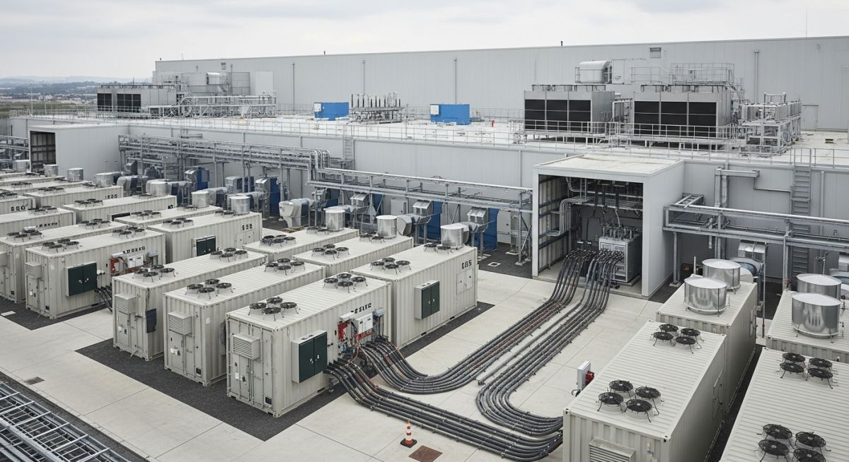
Battery Energy Storage Systems (BESS) for Data Centres: A Technical Guide
In my two decades of experience managing critical infrastructure, I have observed a fundamental shift in how we approach power reliability. The traditional reliance on diesel generators and lead-acid UPS batteries is rapidly evolving toward more sophisticated Battery Energy Storage Systems (BESS). These systems are no longer just backup; they are active components of the power distribution network.
Integrating BESS into a data centre requires a deep understanding of electrochemical kinetics, thermal management, and grid-interactive controls. As we push for higher power densities and carbon-neutral operations, BESS serves as the primary buffer for renewable energy volatility and peak demand management. This guide explores the technical rigor required to deploy these systems effectively.
Key Takeaways for Engineering Teams:
- Understanding the transition from VRLA to Lithium-Ion (LFP) chemistries.
- Optimizing BESS for peak shaving and frequency regulation.
- Navigating IEEE 1547 standards for grid interconnection.
- Implementing advanced thermal runaway mitigation strategies.
Battery Energy Storage Systems (BESS) Fundamentals and Design
BESS Technical Architecture: Battery Energy Storage Systems (BESS) utilize modular electrochemical cells managed by sophisticated Battery Management Systems (BMS) to provide high-speed power injection, governed by IEC 62619 safety protocols.
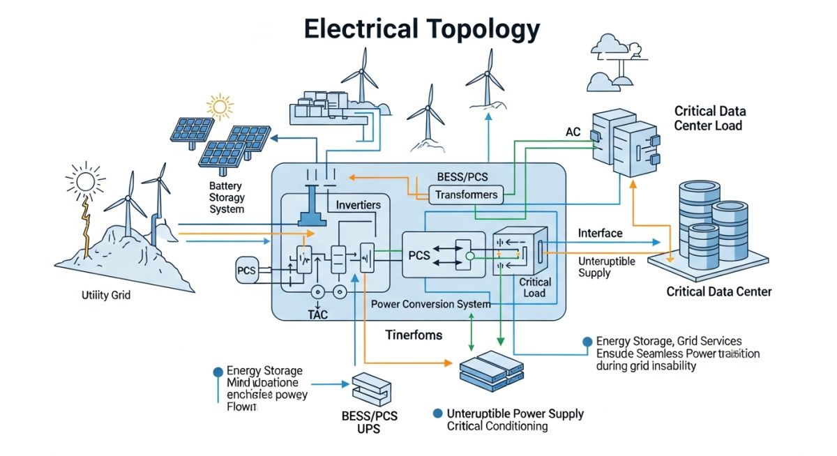
The design of a BESS for a data centre environment is fundamentally different from utility-scale storage. We are dealing with high-availability requirements where the BESS must interface seamlessly with existing Uninterruptible Power Supply (UPS) systems. The primary design challenge lies in the power conversion stage, where bidirectional inverters must handle rapid transitions between charging and discharging modes without introducing harmonic distortion into the critical bus.
Electrochemical Capacity and Discharge Rates
When calculating the required capacity, we must account for the C-rate, which defines the discharge current relative to the nominal capacity. For data centre applications, we typically target a 1C or 2C discharge rate to support the transition period before backup generators reach full load. The energy density calculation follows the basic formula: Energy (kWh) = Power (kW) multiplied by Time (h).
However, we must apply a derating factor to account for Depth of Discharge (DoD) and cycle life degradation. In my experience, limiting the DoD to 80% significantly extends the operational lifespan of Lithium Iron Phosphate (LFP) cells. We also incorporate a State of Health (SoH) monitoring algorithm that tracks internal resistance increases over time, providing predictive maintenance alerts before a cell failure occurs.
Field Warning: Thermal Management Constraints
Data centre BESS installations are highly sensitive to ambient temperature fluctuations. Operating outside the 15 to 30 degrees Celsius range accelerates electrolyte decomposition. Always ensure that the HVAC system for the BESS enclosure is redundant and integrated into the facility’s Building Management System (BMS) to prevent thermal runaway events.
Grid Support and Frequency Regulation
Modern BESS units are capable of providing ancillary services to the grid, such as frequency response and voltage support. By utilizing fast-acting power electronics, the BESS can inject or absorb active power within milliseconds of a frequency deviation. This capability is governed by the NERC reliability standards, which mandate specific response times for grid-connected assets.
The integration of these systems requires a robust communication layer, typically utilizing Modbus TCP/IP or DNP3 protocols, to ensure the BESS controller is synchronized with the utility’s dispatch signals. We must also consider the impact of these rapid power swings on the facility’s internal switchgear, ensuring that circuit breakers are rated for the increased switching frequency and potential fault current contributions from the battery bank.
BESS Operational Trade-offs: Battery Energy Storage Systems (BESS) offer significant operational flexibility for data centres, though they introduce complex maintenance and safety requirements that must be managed through rigorous engineering oversight.
Advantages
- Rapid response time for frequency regulation and grid stability.
- Significant reduction in peak demand charges through load shifting.
- Seamless integration with onsite renewable energy sources like solar PV.
- Extended cycle life compared to traditional VRLA battery strings.
- Modular scalability allowing for incremental capacity expansion.
Disadvantages
- High initial capital expenditure for LFP or NMC chemistries.
- Stringent fire suppression requirements per NFPA 855.
- Complex BMS integration and cybersecurity vulnerabilities.
- Environmental impact of battery disposal and recycling logistics.
- Requirement for specialized HVAC and thermal management infrastructure.
BESS Deployment Scenarios: Battery Energy Storage Systems (BESS) are currently being deployed across diverse data centre environments to solve specific power quality and economic challenges, ranging from remote edge facilities to hyperscale cloud campuses.
Peak Shaving for Hyperscale Facilities
Large-scale data centres utilize BESS to mitigate high utility demand charges by discharging stored energy during peak tariff periods. This application requires high-capacity systems capable of sustained discharge, effectively flattening the facility’s load profile and reducing monthly operational costs by up to 20 percent.
Renewable Energy Smoothing
For data centres co-located with solar or wind farms, BESS acts as a critical buffer to manage the intermittency of renewable generation. By capturing excess energy during peak production and releasing it during low-generation periods, the facility maintains a consistent carbon-neutral power supply for its critical IT loads.
Microgrid Support for Edge Data Centres
In remote locations with unstable grid infrastructure, BESS provides the necessary stability to operate as an islanded microgrid. The system manages voltage and frequency regulation, ensuring that sensitive server hardware remains protected from grid transients and brownouts that are common in rural power distribution networks.
When evaluating Battery Energy Storage Systems (BESS) for mission-critical data centre environments, engineers must prioritize specific performance indicators that dictate reliability and longevity. The selection process involves balancing energy density, cycle life, and discharge rates to ensure the system can handle both transient power spikes and sustained outages without compromising the facility’s Tier-level uptime requirements.
The following table outlines the critical technical parameters for common BESS chemistries utilized in modern data centre power architectures. These values are derived from standard industry testing protocols and reflect the operational constraints typically encountered when integrating storage with existing Uninterruptible Power Supply (UPS) modules. Always verify these specifications against the manufacturer’s data sheets and NFPA 855 compliance requirements before finalizing your procurement strategy.
| Chemistry Type | Energy Density (Wh/kg) | Cycle Life (80% DoD) | Thermal Stability |
|---|---|---|---|
| Lithium Iron Phosphate (LFP) | 100 – 160 | 5,000 – 8,000 | High |
| Nickel Manganese Cobalt (NMC) | 150 – 250 | 2,000 – 4,000 | Moderate |
| Valve Regulated Lead Acid (VRLA) | 30 – 50 | 300 – 500 | Low |
Engineers should note that while LFP offers superior cycle life and thermal safety, the physical footprint requirements differ significantly from traditional VRLA setups. Proper ventilation and fire suppression integration remain mandatory regardless of the chosen chemistry.
The successful deployment of Battery Energy Storage Systems requires a deep understanding of the interconnected electrical and mechanical entities that form the power chain. This matrix maps the primary components, their associated regulatory standards, and their functional roles within a data centre power distribution network, ensuring that all design phases align with industry best practices.
By cross-referencing these entities, project teams can identify potential failure points and optimize the integration of BESS with existing grid-interactive systems. This mapping is essential for maintaining compliance with IEEE standards and ensuring that the BESS architecture supports the facility’s overall sustainability and resilience goals.
| Entity | Standard | Primary Function |
|---|---|---|
| BMS (Battery Management System) | UL 1973 | Cell balancing and thermal monitoring |
| PCS (Power Conversion System) | IEEE 1547 | DC to AC power inversion |
| Fire Suppression System | NFPA 855 | Thermal runaway mitigation |
This matrix serves as a foundational reference for procurement and site commissioning. Always ensure that the selected PCS is compatible with the specific voltage levels of your facility’s UPS bus to prevent harmonic distortion and ensure seamless switching during power events.
BESS Site Integration Compliance: Ensuring the physical and electrical integrity of a Battery Energy Storage System installation requires a rigorous, multi-stage verification process. This checklist provides the necessary checkpoints to validate that your site meets both safety standards and operational performance targets before final energization.
-
☐
Structural Load Verification: Confirm that the floor slab can support the concentrated weight of the battery racks, including seismic bracing requirements per local building codes. -
☐
Thermal Management Validation: Verify that HVAC systems are sized to handle the heat rejection loads of the BESS during both charging and discharging cycles. -
☐
Fire Suppression Alignment: Ensure the fire suppression system is specifically rated for lithium-ion battery fires and is integrated with the facility’s central alarm system. -
☐
Electrical Interconnection: Validate that the PCS output voltage and frequency synchronization match the UPS bus parameters to prevent phase mismatch. -
☐
Communication Protocol Check: Confirm that the BMS communicates effectively with the facility’s DCIM (Data Centre Infrastructure Management) software for real-time monitoring.
Each of these checkpoints must be documented and signed off by a licensed electrical engineer. Failure to verify these parameters can lead to significant operational risks, including thermal runaway or catastrophic failure of the UPS system during a grid disturbance. Always refer to the NFPA guidelines for specific clearance requirements between battery cabinets and other critical infrastructure.
Field Case Study: Real-World Application
Problem: Thermal Instability in Legacy UPS Integration
A major colocation data centre experienced frequent BMS alarms and premature cell degradation after retrofitting a high-density LFP battery array into an existing, poorly ventilated UPS room.
- Inadequate ambient temperature control leading to accelerated chemical aging.
- Lack of proper communication between the legacy UPS controller and the new BESS.
- Insufficient clearance for maintenance access, causing airflow blockages.
- Incompatible charging profiles causing voltage spikes during float mode.
Outcome: Optimized Thermal and Control Architecture
The facility achieved a 40% increase in battery lifespan and eliminated unplanned downtime by implementing a comprehensive system overhaul.
- Installed dedicated precision cooling units to maintain a constant 22 degrees Celsius.
- Upgraded the communication gateway to allow seamless integration between the BESS and DCIM.
- Reconfigured the rack layout to meet manufacturer-recommended airflow clearances.
- Standardized charging parameters to align with the specific chemistry requirements.
This case highlights that BESS integration is not merely a plug-and-play electrical task; it requires a holistic approach to thermal management and control system synchronization. My recommendation is to always conduct a thermal load study before finalizing the physical placement of battery cabinets in legacy environments.
Frequently Asked Engineering Questions
How does BESS improve data centre power resilience?
- Instantaneous response to power quality events without relying on diesel generators.
- Extended ride-through time during utility transitions.
- Peak shaving capabilities that reduce the stress on the facility’s primary electrical infrastructure.
What are the primary safety risks of lithium-ion BESS?
- Advanced BMS monitoring to detect early signs of cell degradation.
- Robust fire suppression systems designed for high-energy battery fires.
- Strict physical separation and fire-rated enclosures to prevent fire propagation.
Can BESS be used for renewable energy integration?
- Shift renewable energy usage to periods of high demand.
- Stabilize the local microgrid by providing frequency regulation services.
- Reduce reliance on carbon-intensive grid power during peak pricing windows.
How does BESS impact UPS maintenance schedules?
- Regular firmware updates for the BMS and PCS controllers.
- Periodic thermal imaging of electrical connections to identify high-resistance points.
- Calibration of state-of-charge (SoC) and state-of-health (SoH) algorithms.
What is the typical ROI for BESS in data centres?
- Avoidance of peak demand charges from utility providers.
- Participation in demand response programs that pay for grid stability services.
- Reduced operational costs through improved energy efficiency and lower maintenance requirements compared to legacy lead-acid systems.
Are there specific standards for BESS commissioning?
Complete Course on
Piping Engineering
Check Now
Key Features
- 125+ Hours Content
- 500+ Recorded Lectures
- 20+ Years Exp.
- Lifetime Access
Coverage
- Codes & Standards
- Layouts & Design
- Material Eng.
- Stress Analysis

📚 Recommended Resources: Battery Energy Storage Systems
Read these Guides
- 📄 Economics of Battery Energy Storage Systems: A Comprehensive Financial Guide
- 📄 Grid Applications of Battery Energy Storage Systems: A Technical Guide
- 📄 Battery Energy Storage Systems: Engineering Design and Operational Fundamentals
- 📄 Battery Energy Storage Systems: A Comprehensive Engineering Design Guide