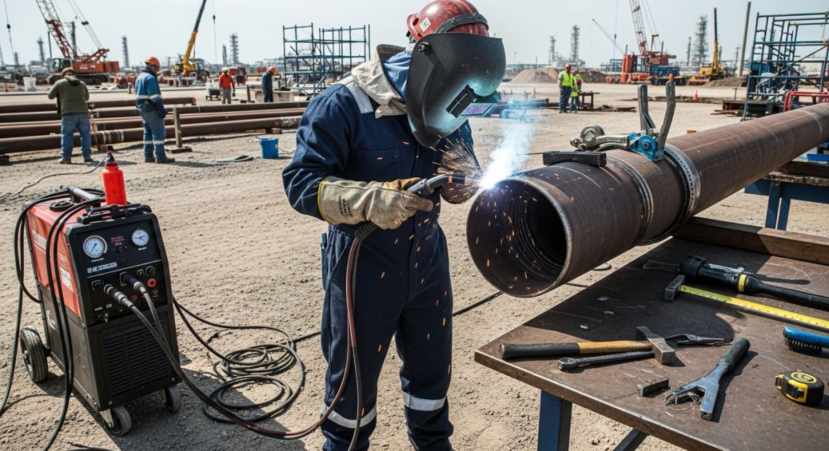
General Requirements for Field Welding in Piping Systems
In my two decades of managing piping construction, I have learned that the difference between a successful project and a catastrophic failure often lies in the execution of field welds. Unlike shop fabrication, where environmental variables are controlled, field welding demands rigorous adherence to site-specific procedures to mitigate the risks of hydrogen cracking, lack of fusion, and atmospheric contamination.
When we talk about general requirements for field welding, we are not just discussing the act of joining two pipes; we are managing a complex intersection of material science, welder qualification, and environmental protection. Whether you are working on high-pressure steam lines or cryogenic process piping, the fundamental requirements remain non-negotiable.
Key Takeaways for Field Success:
- Mandatory verification of WPS (Welding Procedure Specification) against site-specific base materials.
- Strict control of preheat and interpass temperatures to prevent brittle fracture.
- Implementation of real-time NDT (Non-Destructive Testing) protocols for high-risk joints.
- Environmental shielding requirements for wind speeds exceeding 5 mph.
Technical Standards for General Requirements for Field Welding
Field Welding Standards: The technical framework governing the qualification of personnel, materials, and procedures to maintain code-compliant pressure boundary integrity under variable site conditions.
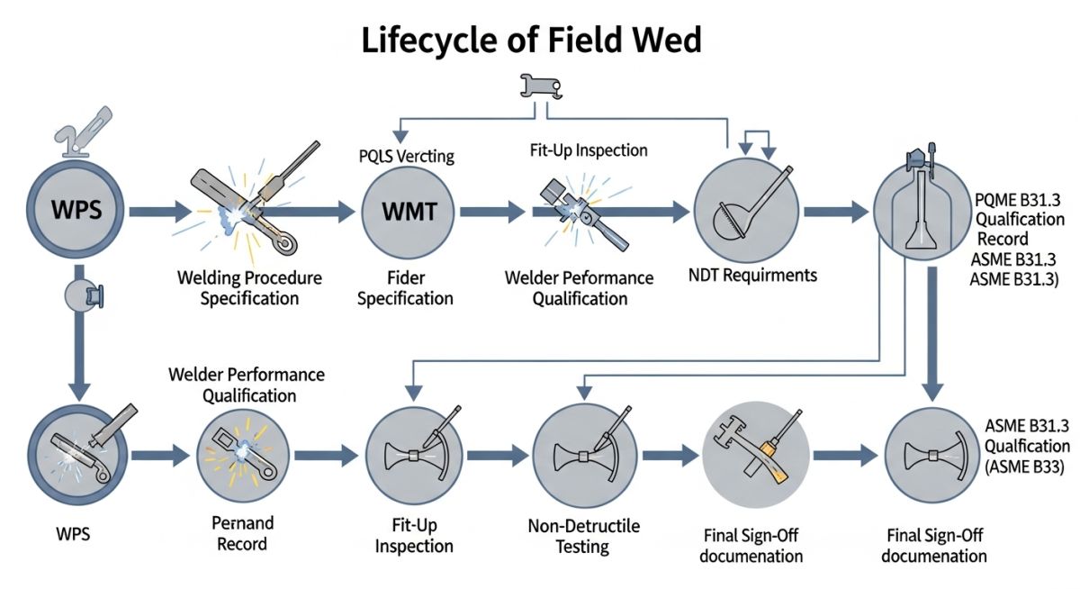
When executing field welds, the primary governing document is ASME B31.3. This code dictates that all welding must be performed in accordance with a qualified Welding Procedure Specification (WPS). In my experience, the most common failure point is the disconnect between the WPS and the actual field conditions, such as ambient temperature or moisture levels.
Material Compatibility and Preheat Requirements
For carbon steel piping, particularly those with high carbon equivalents, preheating is not optional. The AWS D1.1 standard provides the baseline for calculating the required preheat temperature based on the material thickness and hydrogen content of the filler metal. If the ambient temperature drops below 32 degrees Fahrenheit, the code requires the base metal to be heated to at least 50 degrees Fahrenheit for a distance of 3 inches in all directions from the weld joint.
Field Warning: Hydrogen Cracking
Hydrogen-induced cracking (HIC) is the silent killer of field welds. Always ensure that low-hydrogen electrodes (such as E7018) are stored in rod ovens at 250-300 degrees Fahrenheit. If an electrode is exposed to atmospheric moisture for more than four hours, it must be re-baked or discarded to prevent porosity and hydrogen embrittlement.
Stress Parameters and Joint Geometry
The root opening and bevel angle are critical for achieving full penetration. For a standard V-groove weld, a root opening of 1/16 to 1/8 inch is typical. However, field fit-up often results in excessive gaps. If the root opening exceeds the WPS tolerance, the welder must not attempt to “bridge” the gap with excessive heat, as this leads to heat-affected zone (HAZ) degradation and potential stress corrosion cracking.
We calculate the heat input using the formula: Heat Input = (Voltage x Amperage x 60) / (Travel Speed x 1000). Maintaining this value within the range specified in the Procedure Qualification Record (PQR) is essential. If the heat input is too high, the grain structure of the HAZ coarsens, significantly reducing the impact toughness of the joint.
Field Welding Trade-offs: The strategic evaluation of site-based fabrication versus shop-prefabrication regarding cost, quality control, and project schedule flexibility.
Advantages
- Allows for final adjustments to piping geometry to accommodate site interferences.
- Eliminates the need for complex logistics of transporting large, pre-fabricated spools.
- Enables immediate repair of damaged components without waiting for shop replacement.
- Reduces the number of flanged connections, thereby minimizing potential leak paths.
Disadvantages
- High susceptibility to environmental variables like wind, rain, and humidity.
- Increased difficulty in maintaining consistent NDT quality compared to shop conditions.
- Higher labor costs due to specialized field equipment and safety requirements.
- Greater risk of human error due to fatigue and challenging physical access.
Field Welding Implementation: The practical deployment of welding procedures across diverse industrial sectors to ensure structural and pressure-retaining integrity.
Oil and Gas Pipeline Infrastructure
Field welding is the backbone of cross-country pipeline construction, where long-distance segments must be joined in remote environments. We utilize automated orbital welding systems to maintain consistent penetration and fusion, ensuring the pipeline can withstand high-pressure surges and thermal expansion cycles over decades of service.
Refinery Turnaround and Maintenance
During refinery shutdowns, field welding is essential for the rapid replacement of corroded piping sections and the integration of new process units. The challenge here is working within confined spaces while adhering to strict hot-work permits and ensuring that the new welds meet the original design pressure ratings of the existing system.
Power Plant Steam Piping
High-temperature, high-pressure (HTHP) steam lines require specialized welding techniques, including stringent preheat and post-weld heat treatment (PWHT) protocols. Field welding in these environments demands precise control over the cooling rate to prevent the formation of brittle martensite, which could lead to catastrophic failure under cyclic thermal loading.
In my two decades of field experience, I have observed that the primary cause of weld failure is the misinterpretation of essential variables defined in the Welding Procedure Specification (WPS). When executing field welds, the engineer must ensure that the actual site conditions—such as ambient temperature, wind velocity, and base metal thickness—align perfectly with the qualified ranges established during the Procedure Qualification Record (PQR) phase. The following table outlines the critical parameters that require constant monitoring by the welding inspector to maintain compliance with ASME B31.3.
It is not enough to simply have a qualified procedure; the field team must verify that the heat input, interpass temperature, and shielding gas flow rates are strictly controlled. Deviations in these parameters, even if they seem minor, can lead to localized hardening or loss of toughness in the heat-affected zone (HAZ), potentially compromising the integrity of the entire piping system under high-pressure service conditions.
| Parameter | ASME B31.3 Reference | Field Control Requirement |
|---|---|---|
| Preheat Temperature | Table 330.1.1 | Minimum temperature must be maintained 3 inches from the weld joint. |
| Interpass Temperature | Section 330.1.4 | Maximum limit must not be exceeded to prevent grain growth. |
| Shielding Gas Flow | Section 328.2.1 | Flow must be verified at the nozzle using a calibrated rotameter. |
| Post-Weld Heat Treatment | Table 331.1.1 | Soak time and heating rate must be recorded via thermocouple logs. |
The complexity of field welding requires a structured approach to documentation and material traceability. As an engineer, I rely on this matrix to ensure that every weld is mapped to its corresponding material test report (MTR) and welder performance qualification (WPQ). This level of rigor is mandatory for high-energy piping systems where the consequences of a weld failure are catastrophic.
By cross-referencing these entities, we create a digital twin of the piping system’s integrity. This matrix serves as the backbone for the final turnover package, ensuring that the client has full visibility into the quality assurance processes performed during the construction phase. Always ensure that the AWS and ASME standards are the latest editions as specified in the project contract documents.
| Entity | Acronym | Standard Reference |
|---|---|---|
| Welding Procedure Specification | WPS | ASME Section IX |
| Procedure Qualification Record | PQR | ASME Section IX |
| Welder Performance Qualification | WPQ | ASME Section IX |
| Non-Destructive Examination | NDE | ASME B31.3 Chapter VI |
Field welding success is predicated on meticulous preparation. Before the first arc is struck, the site supervisor must verify that the environment, equipment, and personnel are fully prepared. In my experience, skipping these verification steps is the fastest route to rework and project delays. Use this checklist to ensure that your field operations remain compliant with ASME B31.3 requirements.
- ✓ Verify that the WPS is available at the work face and matches the base metal P-number.
- ✓ Confirm that the welder has a valid WPQ for the specific process and position being used.
- ✓ Inspect the fit-up for root opening and bevel angle against the approved isometric drawings.
- ✓ Check that the base metal is free of moisture, oil, grease, and heavy oxidation within 1 inch of the weld.
- ✓ Ensure that wind protection is in place if the wind speed exceeds 5 mph for gas-shielded processes.
- ✓ Validate that the preheat temperature is measured using a calibrated contact pyrometer or temperature-indicating crayon.
- ✓ Confirm that the filler metal is stored in a heated rod oven if required by the manufacturer.
Once these items are verified, the inspector should sign off on the weld map. Remember that documentation is as important as the physical weld; if it isn’t recorded, it didn’t happen in the eyes of the code inspector. Always maintain a clear chain of custody for all NDE reports and heat number tracking logs to ensure full traceability for the life of the asset.
The Problem: High-Pressure Steam Line Failure
During a high-pressure steam line installation, we encountered a series of recurring porosity issues in the root pass of 12-inch chrome-moly piping.
- Inadequate shielding gas coverage due to high-velocity crosswinds in the pipe rack.
- Moisture contamination on the bevel surfaces caused by overnight condensation.
- Incorrect electrode storage leading to hydrogen-induced cracking risks.
- Lack of proper preheat maintenance during the tack welding process.
The Outcome: Corrective Action and Success
By implementing a strict environmental control protocol, we eliminated the defects and achieved a 100% pass rate on subsequent radiographic testing.
- Installed portable wind-shielding enclosures around all active weld joints.
- Mandated a 250-degree Fahrenheit preheat for moisture removal prior to fit-up.
- Implemented a “just-in-time” rod distribution system from the central oven.
- Increased the frequency of interpass temperature monitoring to ensure stability.
My recommendation for similar projects is to prioritize environmental control as a primary welding variable. Do not assume that standard shop practices will suffice in an uncontrolled field environment; you must adapt your setup to the specific site conditions to maintain the integrity required by ASME B31.3.
How do I determine the correct preheat temperature for a specific material?
- Always verify the material thickness against the table requirements.
- Consider the ambient temperature; if it is below 32 degrees Fahrenheit, additional preheat is often required regardless of thickness.
- Ensure the preheat is applied uniformly around the joint to prevent thermal stress.
- Use calibrated temperature-indicating crayons or contact pyrometers to verify the temperature before starting the arc.
What are the consequences of exceeding the interpass temperature?
- Loss of corrosion resistance in stainless steel grades due to carbide precipitation.
- Increased risk of hot cracking during the cooling phase.
- Reduction in yield strength due to over-tempering of the base metal.
- Failure to meet the Charpy V-notch impact test requirements defined in the project specifications.
When is Post-Weld Heat Treatment (PWHT) mandatory?
- Required for high-carbon steels and certain alloy steels to prevent brittle fracture.
- Necessary for service environments prone to stress corrosion cracking.
- Must be performed according to a qualified procedure that specifies heating and cooling rates.
- Requires continuous temperature recording to ensure the soak time is achieved throughout the entire weld thickness.
How do I handle wind interference during gas-shielded welding?
- Construct wind-shielding barriers using fire-retardant tarps or metal sheets.
- Ensure the barrier is positioned to block the wind from all directions relative to the weld joint.
- Avoid using excessive gas flow rates to compensate for wind, as this can create turbulence and draw in more air.
- If wind speeds cannot be controlled, consider switching to a shielded metal arc welding (SMAW) process, which is less sensitive to wind.
What documentation is required for a field weld turnover package?
- Weld map showing the location and unique identifier of every field weld.
- Welder identification linked to each specific weld joint.
- Material Test Reports (MTRs) for all pipe and fitting components.
- NDE reports (Radiographic, Ultrasonic, or Dye Penetrant) with clear acceptance criteria.
- PWHT charts and calibration records for all heating equipment used.
How do I verify the calibration of welding equipment in the field?
- Use a calibrated shunt or clamp-on ammeter to verify current and voltage.
- Check calibration stickers on all machines to ensure they are within the annual validation period.
- Verify the accuracy of gas flow meters using a portable rotameter at the torch nozzle.
- Document all calibration checks in the project quality log to demonstrate compliance during third-party audits.
📚 Recommended Resources: Field Welding
Read these Guides
🎓 Advanced Training


Complete Course on
Piping Engineering
Check Now
Key Features
- 125+ Hours Content
- 500+ Recorded Lectures
- 20+ Years Exp.
- Lifetime Access
Coverage
- Codes & Standards
- Layouts & Design
- Material Eng.
- Stress Analysis
