
What is Fillet Welding? Parts, Types, Symbols, and Applications
In my 20 years of managing piping and structural fabrication projects, I have noticed that engineers often underestimate the complexity of a simple fillet weld. We see them everywhere—from structural steel pipe racks to heavy equipment foundations. Yet, a misunderstanding of throat thickness or joint configuration can lead to catastrophic structural failures. Let me take you through the exact engineering principles, calculations, and field realities of this fundamental welding technique.
Key Engineering Takeaways
- Understand the geometric relationship where throat thickness equals 0.707 times the leg length.
- Learn why fillet welds are designed to fail in shear across the theoretical throat.
- Identify the correct welding symbols to prevent costly fabrication shop reworks.
- Compare the cost-to-strength benefits of fillet welds versus full-penetration butt welds.
What is Fillet Welding and How Does It Work?
[Fillet Welding Mechanics]: [The fillet welding process deposits a triangular bead of weld metal directly into the corner of two intersecting structural members without requiring prior edge preparation or beveling of the base metals.]
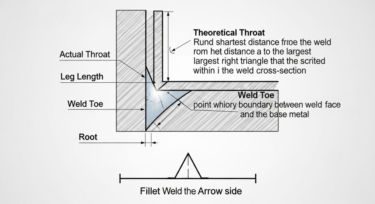
To design a reliable joint, we must first break down the physical anatomy of the weld. A standard fillet weld consists of several distinct parts:
- Root: The deepest point of penetration where the weld metal intersects the base metal surfaces.
- Toe: The boundary line where the weld face meets the base metal.
- Face: The exposed outer surface of the weld.
- Leg Length: The distance from the root to the toe of the weld.
- Throat Thickness: The shortest distance from the root to the face of the weld.
In my design reviews, I always emphasize that the strength of a fillet weld is entirely dependent on its effective throat thickness. For a standard equal-leg fillet weld with a leg size designated as “z”, the theoretical throat “a” is calculated using basic trigonometry: throat thickness equals leg length multiplied by the cosine of 45 degrees, which simplifies to a = 0.707 times z. If a welder deposits a weld with an 8mm leg size, the effective throat that actually resists structural loads is only 5.66mm. Designing based on leg size instead of throat thickness is a common mistake that can compromise structural integrity.
All structural designs must comply with AWS D1.1 Structural Welding Code for steel structures, or ASME Section IX for pressure vessels and piping systems.
CRITICAL FIELD WARNING: THE CONVEXITY TRAP
Excessive weld convexity does not add structural strength. In fact, highly convex fillet welds create sharp transitions at the weld toes, acting as severe stress risers under cyclic loading. This often leads to premature fatigue cracking. Always aim for a flat or slightly concave profile in dynamic applications.
How Do We Calculate Fillet Welding Strength?
[Fillet Weld Strength Calculation]: [The structural capacity of a fillet weld is determined by calculating the allowable shear stress across its theoretical throat area in accordance with AISC and AWS design specifications.]
Let us walk through a practical engineering calculation. Suppose we have a structural T-joint subjected to a longitudinal shear force. We are using an E70XX electrode, which has a minimum tensile strength of 70,000 psi (70 ksi).
According to AISC specifications, the allowable shear stress (F_w) on the weld throat is:
F_w = 0.30 * F_exx
For an E70 electrode:
F_w = 0.30 * 70,000 psi = 21,000 psi (145 MPa)
The allowable load per unit length (P) of the weld is then calculated by multiplying this allowable stress by the throat area per unit length:
P = F_w * a = F_w * 0.707 * z
If we use a 1/4 inch (6.35 mm) leg size (z):
P = 21,000 psi * 0.707 * 0.25 inches = 3,711 pounds per linear inch of weld
This straightforward calculation forms the basis of structural weld sizing. When I audit fabrication shops, I verify that the actual weld sizes match these design calculations to prevent under-welding.
Minimum Fillet Weld Sizes (AWS D1.1)
| Base Metal Thickness of Thicker Part (Inches) | Minimum Leg Size of Fillet Weld (Inches) | Minimum Leg Size (mm) |
|---|---|---|
| To 1/4 inclusive | 1/8 | 3.2 |
| Over 1/4 to 1/2 | 3/16 | 4.8 |
| Over 1/2 to 3/4 | 1/4 | 6.4 |
| Over 3/4 | 5/16 | 7.9 |
| Parameter / Feature | Fillet Welding | Butt Welding | Applicable Standard Reference |
|---|---|---|---|
| Joint Configuration | T-joints, lap joints, corner joints | Co-planar joints (edge-to-edge) | AWS D1.1 Clause 4 |
| Edge Preparation | None required (square edges) | Beveling, V-groove, U-groove required | ASME B31.3 Chapter V |
| Primary Stress State | Shear stress on throat | Tension or compression | AISC 360 Chapter J |
| NDT Inspection Methods | Visual (VT), Magnetic Particle (MT), Penetrant (PT) | Radiography (RT), Ultrasonic (UT) | ASME Section V |
How to Inspect Fillet Welds on Site?
[Fillet Weld Inspection Protocol]: [On-site quality assurance of fillet welds requires systematic visual and non-destructive examination to verify leg size, throat thickness, profile contour, and the absence of surface defects like undercut or porosity.]
During my field audits, I use a strict verification protocol to ensure that the welding team does not cut corners. Here is the exact checklist I use on-site before, during, and after the welding process.
Field Inspection Checklist
-
Verify Fit-Up Tolerance: Ensure the root gap does not exceed 1/16 inch (1.6 mm) prior to welding. Gaps up to 3/16 inch require an increase in the fillet weld leg size by the amount of the gap, as specified in AWS D1.1. -
Check Leg Length and Throat: Use a calibrated fillet weld gauge to measure both leg lengths. Unequal legs must be evaluated against design requirements. -
Inspect Profile Contour: Confirm the weld profile is flat or slightly concave. Reject any welds showing excessive convexity or overlap at the toes. -
Detect Surface Defects: Perform 100% visual inspection for undercut, surface porosity, cracking, or incomplete fusion along the weld toes. -
Verify Welder Qualifications: Confirm that the welder is certified for the specific position (e.g., 2F, 3F, 4F) and process under ASME Section IX.
Field Case Study: Real-World Application
The Problem: Structural Bracket Failure Under Cyclic Loading
During a routine plant shutdown inspection at a petrochemical facility, I discovered severe cracking along the fillet weld toes of a heavy pipe support bracket. The bracket was subjected to high-frequency vibration from an adjacent reciprocating compressor. The original fabricator had deposited highly convex fillet welds with significant undercut at the toes. This poor profile acted as a severe stress concentration point, initiating fatigue cracks that propagated through the heat-affected zone (HAZ) of the structural steel.
The Outcome: Remediation and Profile Optimization
I ordered the immediate removal of the cracked welds via carbon arc gouging, followed by grinding to clean metal. We redesigned the joint to use a slightly concave fillet weld profile, ensuring a smooth transition to the base metal. We also specified a magnetic particle inspection (MT) post-weld to confirm zero surface defects. The compressor support has now been operating for over five years without any signs of degradation, proving that weld profile control is just as important as weld size.
My direct recommendation for any dynamic or cyclic loading application is to specify a concave fillet weld profile and mandate magnetic particle testing (MT) or liquid penetrant testing (PT) to catch micro-cracks before they propagate.
Frequently Asked Engineering Questions
What is the difference between leg length and throat thickness?
When should I choose a fillet weld over a butt weld?
What do the numbers on a fillet welding symbol mean?
Why do fillet welds fail in shear?
Can a fillet weld be non-destructively tested using radiography?
What is the maximum fit-up gap allowed for a fillet weld?
Complete Course on
Piping Engineering
Check Now
Key Features
- 125+ Hours Content
- 500+ Recorded Lectures
- 20+ Years Exp.
- Lifetime Access
Coverage
- Codes & Standards
- Layouts & Design
- Material Eng.
- Stress Analysis