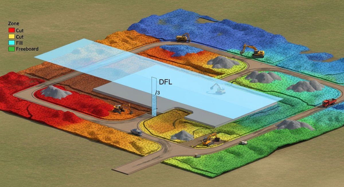
Recommended Workflow for Establishing FPL and Estimating Cut/Fill Quantities
In my two decades of managing large-scale industrial site developments, I have observed that the most common cause of project delays and budget overruns is a poorly defined Flood Protection Level (FPL). Establishing the FPL is not merely a regulatory checkbox; it is the foundational decision that dictates your entire earthworks strategy, drainage design, and long-term asset resilience.
This guide outlines the rigorous, step-by-step workflow I use to transition from raw DTM data to an optimized cut-and-fill balance. By aligning your FPL with site-specific constraints and infrastructure levels early in the FEED phase, you mitigate the risk of massive, unplanned soil import or export costs later in the construction cycle.
Key Takeaways
- Always validate DTM/TIN surfaces against site-verified benchmarks before establishing the FPL.
- Freeboard selection must account for local climate resilience factors, not just minimum code requirements.
- Iterative cut/fill analysis is the only way to achieve a cost-neutral earthworks balance.
- Early integration of adjoining infrastructure levels prevents costly drainage bottlenecks.
Establishing FPL and Site Grading Workflow
Flood Protection Level Integration: The technical process of reconciling hydrological flood modeling with site-specific grading requirements to ensure structural integrity and regulatory compliance.
The workflow begins with the acquisition of high-resolution Digital Terrain Model (DTM) or Triangulated Irregular Network (TIN) data. In my experience, relying on legacy survey data is a recipe for disaster. I mandate a site-specific LiDAR or drone-based survey to ensure the base topography reflects current conditions, especially in areas prone to erosion or recent land movement.
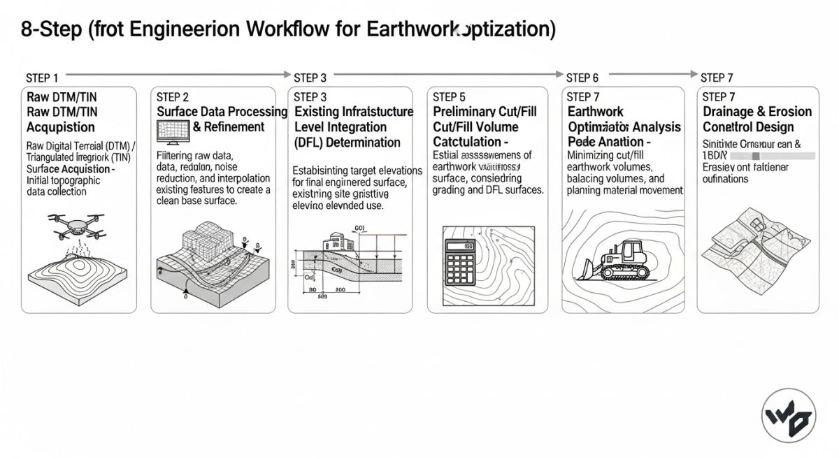
Integrating Adjoining Infrastructure Levels
Once the DTM is established, we must map the adjoining infrastructure. This includes existing road crowns, rail spurs, and utility corridors. If your site FPL is set significantly higher than the surrounding infrastructure, you create a “bathtub” effect, which complicates stormwater management and increases the cost of site access ramps.
I use the following calculation logic for determining the minimum site elevation (E_min):
Where:
H_flood = 100-year or 500-year flood elevation (per FEMA or local authority)
F_board = Required freeboard (typically 300mm to 600mm)
S_margin = Safety margin for climate change/subsidence
Performing Cut and Fill Analysis
With the FPL established, the next phase is the iterative cut/fill analysis. The goal is to minimize the “haul distance” and the volume of imported fill. I utilize Civil 3D or similar platforms to generate a mass-haul diagram. This diagram is the primary tool for identifying where we can balance the site by moving material from high-elevation cut zones to low-elevation fill zones.
Field Warning: Soil Swell and Shrinkage Factors
Never assume a 1:1 volume ratio for cut and fill. You must apply a shrinkage factor for clay-heavy soils (typically 10-15%) and a swell factor for rock excavation. Failing to account for these geotechnical properties will lead to a significant shortfall in material, forcing expensive emergency procurement of fill.
When evaluating multiple FPL options, I perform a sensitivity analysis. If raising the FPL by 100mm results in a 20% increase in imported fill volume, we must evaluate if the cost of that fill is justified by the reduction in flood risk insurance premiums or potential damage costs. This is where engineering judgment meets financial reality.
Flood Protection Level Optimization: The strategic evaluation of site grading alternatives to balance regulatory compliance, capital expenditure, and long-term operational resilience.
Advantages
- Reduced long-term flood insurance premiums and risk exposure.
- Optimized earthworks reduce total project mobilization and haulage costs.
- Improved site drainage performance by establishing positive gradients early.
- Enhanced regulatory approval speed through proactive flood mitigation planning.
- Increased asset longevity by preventing moisture-related foundation degradation.
Disadvantages
- Higher initial capital expenditure for significant site-wide fill operations.
- Potential for increased slope stability risks if fill embankments are too steep.
- Complexity in managing drainage transitions between elevated and natural ground.
- Requirement for extensive geotechnical testing to validate fill material suitability.
- Risk of creating localized drainage bottlenecks if adjoining sites are not aligned.
Industrial Site Grading Applications: The practical implementation of FPL and earthworks strategies across diverse heavy industrial and infrastructure sectors.
Greenfield Petrochemical Facilities
In large-scale petrochemical projects, the FPL is the primary driver for pipe rack elevation and equipment foundation design. By establishing a precise FPL, we ensure that critical process equipment remains operational during extreme weather events, while simultaneously balancing the massive earthwork volumes required for tank farm pads.
Coastal Power Generation Plants
Coastal sites face the dual challenge of storm surges and sea-level rise. We apply rigorous FPL modeling to determine the necessary elevation for turbine halls and switchyards, often requiring significant structural fill and reinforced retaining walls to maintain site stability against tidal forces.
Logistics and Distribution Hubs
For massive distribution centers, the FPL must be balanced against the need for flat, expansive loading dock areas. We use iterative cut/fill analysis to create large, level platforms that meet flood safety standards without requiring excessive soil import, which would otherwise render the project economically unviable.
Mining Infrastructure Development
Mining sites often involve complex topography where the FPL must be integrated with tailings management and haul road networks. Our workflow ensures that the site grading plan accounts for both the flood protection of processing plants and the efficient movement of ore, minimizing the environmental footprint of earthworks.
When establishing the Finished Platform Level (FPL), engineers must reconcile theoretical design volumes with the practical realities of soil behavior. The following table outlines the critical parameters that influence the accuracy of cut and fill estimations, specifically focusing on the transition from raw Digital Terrain Model (DTM) data to final site grading volumes. These factors are governed by ASCE guidelines for site development and earthwork management.
It is imperative to account for the swell and shrinkage factors inherent in different soil types, as these significantly alter the net volume balance. Failure to apply these coefficients during the initial FPL iteration often leads to costly borrow-pit requirements or excessive spoil disposal on-site. Always verify these values against local geotechnical reports before finalizing your earthwork model.
| Parameter | Typical Range | Impact on FPL |
|---|---|---|
| Shrinkage Factor | 10% to 25% | Increases required fill volume |
| Swell Factor | 5% to 15% | Increases haulage volume for cut |
| Compaction Ratio | 0.85 to 0.95 | Directly affects platform settlement |
The following matrix maps the essential technical entities required for a robust FPL workflow. By aligning these components with international standards, we ensure that the site grading strategy remains defensible during regulatory audits and construction execution. Each entity serves as a foundational pillar for the ISO-compliant site development process.
Engineers should utilize this matrix to cross-reference their project documentation. Ensuring that every DTM node, flood level datum, and infrastructure interface is accounted for prevents the common pitfall of “level-creep,” where the FPL is adjusted incrementally without re-evaluating the entire site drainage and earthwork balance.
| Entity | Standard Reference | Primary Function |
|---|---|---|
| DTM/TIN Surface | ASTM D6236 | Baseline topography modeling |
| Flood Level (DFL) | ASCE 24 | Risk mitigation threshold |
| Freeboard | FEMA Guidelines | Safety margin for uncertainty |
Establishing the FPL is not merely a desktop exercise; it requires rigorous field verification to ensure that the theoretical model matches the physical reality of the site. I have developed this checklist to guide engineers through the critical validation steps necessary to prevent costly rework during the earthworks phase.
-
Benchmark Verification: Confirm all site benchmarks against national geodetic survey markers to ensure vertical datum consistency. -
Infrastructure Interface: Validate existing road and utility invert levels against the proposed FPL to ensure gravity drainage feasibility. -
Geotechnical Review: Verify that the proposed cut slopes and fill embankments align with the soil bearing capacity defined in the ASTM report. -
Floodplain Compliance: Cross-check the final FPL against local authority flood maps to ensure the required freeboard is maintained across the entire site footprint. -
Volume Reconciliation: Perform a final mass-haul analysis to ensure that the cut/fill balance is optimized for on-site material reuse.
By systematically working through these checkpoints, you minimize the risk of encountering unforeseen site conditions that could jeopardize the project schedule. Remember that the FPL is the most critical elevation on your site plan; any error here propagates through every subsequent design discipline, including structural foundations and underground piping networks.
Field Case Study: Real-World Application
The Challenge: Inaccurate DTM and Drainage Conflict
During a recent industrial expansion project, the initial FPL was set based on an outdated DTM, leading to a significant discrepancy between the design model and the actual site topography.
- Existing site drainage inverts were 0.5 meters higher than the model indicated.
- The proposed FPL would have resulted in a “bowl” effect, trapping surface water.
- Geotechnical data suggested higher-than-anticipated shrinkage, requiring more fill than budgeted.
The Outcome: Optimized Grading and Cost Savings
By re-surveying the site and adjusting the FPL to accommodate the true drainage constraints, we successfully mitigated the risk of flooding and optimized the earthworks.
- Reduced imported fill requirements by 15% through strategic site balancing.
- Achieved a 100% gravity-fed drainage solution, eliminating the need for expensive pump stations.
- Completed the project 3 weeks ahead of schedule by avoiding mid-construction design changes.
My recommendation for similar projects is to always prioritize a high-resolution drone survey or LiDAR scan over legacy topographic data. The cost of accurate data is negligible compared to the expense of re-grading a site once construction has commenced.
Frequently Asked Engineering Questions
How does freeboard impact the overall FPL?
- It provides a margin for error in extreme weather events.
- It ensures that critical infrastructure remains operational during peak flood stages.
- It is a non-negotiable requirement for insurance and regulatory compliance.
What is the role of DTM in earthwork estimation?
- It allows for precise cut and fill volume quantification.
- It enables the visualization of drainage patterns and slope stability.
- It facilitates the optimization of mass-haul diagrams to minimize material transport costs.
How do I handle soil shrinkage in calculations?
- Always obtain a geotechnical report to determine the specific shrinkage factor for your soil type.
- Apply the factor to the fill volume calculation to determine the required borrow amount.
- Monitor compaction levels during construction to ensure the design density is achieved.
Why is infrastructure interface validation critical?
- Ensures gravity drainage systems function as designed.
- Prevents the creation of low spots that could lead to ponding.
- Maintains accessibility for heavy vehicles and site logistics.
What are the risks of an incorrect FPL?
- Increased project costs due to massive earthwork re-grading.
- Potential for site flooding during extreme weather events.
- Legal and insurance liabilities if the site fails to meet flood protection standards.
How do I optimize earthworks for cost?
- Use software to perform automated volume calculations for multiple FPL scenarios.
- Prioritize on-site material reuse to reduce haulage and disposal costs.
- Consider the impact of soil properties on the overall earthwork balance.
Complete Course on
Piping Engineering
Check Now
Key Features
- 125+ Hours Content
- 500+ Recorded Lectures
- 20+ Years Exp.
- Lifetime Access
Coverage
- Codes & Standards
- Layouts & Design
- Material Eng.
- Stress Analysis
