Drainage Design Considerations for Data Centres: A Technical Guide
In my two decades of experience designing mission-critical infrastructure, I have learned that the most sophisticated server cooling systems are useless if the facility is compromised by a 100-year storm event. Drainage design considerations for data centres go far beyond simple pipe sizing; they represent the first line of defense for the facility’s physical integrity.
When we approach site civil engineering for these projects, we must balance high-density equipment loads with stringent environmental discharge requirements. A failure in the drainage network can lead to catastrophic basement flooding, foundation settlement, or the loss of critical utility connections. This guide explores the technical rigor required to maintain operational continuity through robust hydraulic management.
Key Takeaways for Engineering Teams:
- Prioritize site grading to ensure positive drainage away from critical power and cooling infrastructure.
- Implement redundant detention systems to manage peak flow rates during extreme weather events.
- Integrate EPA-compliant oil-water separators for backup generator fuel containment areas.
- Verify that all drainage outfalls meet local municipal hydraulic capacity and water quality standards.
Technical Drainage Design Considerations for Data Centres
Stormwater Infrastructure Integrity: The application of hydraulic modeling and civil engineering principles to manage site runoff, ensuring that peak discharge rates do not exceed pre-development levels while protecting mission-critical assets from inundation.
Designing for data centres requires a departure from standard commercial site practices. We must calculate the Time of Concentration (Tc) with extreme precision, often utilizing the Rational Method for smaller sites or TR-55 for larger, complex catchments. The primary objective is to prevent the “ponding” effect near generator yards and electrical substations, where even minor water ingress can trigger a site-wide shutdown.
Hydraulic Capacity and Pipe Sizing
When sizing the primary drainage network, I always apply a factor of safety to the Manning’s Equation calculations. The formula for velocity is V = (1.486/n) * R^(2/3) * S^(1/2), where ‘n’ represents the Manning roughness coefficient. For high-density polyethylene (HDPE) or reinforced concrete pipe (RCP), we typically assume an ‘n’ value of 0.011 to 0.013.
Field Warning: Hydraulic Bottlenecks
Never underestimate the impact of debris accumulation in drainage inlets. In my experience, data centre sites with large cooling tower arrays often face unique challenges with drift and particulate matter. Ensure that all catch basins are equipped with high-capacity, easily accessible sediment traps to prevent downstream pipe clogging.
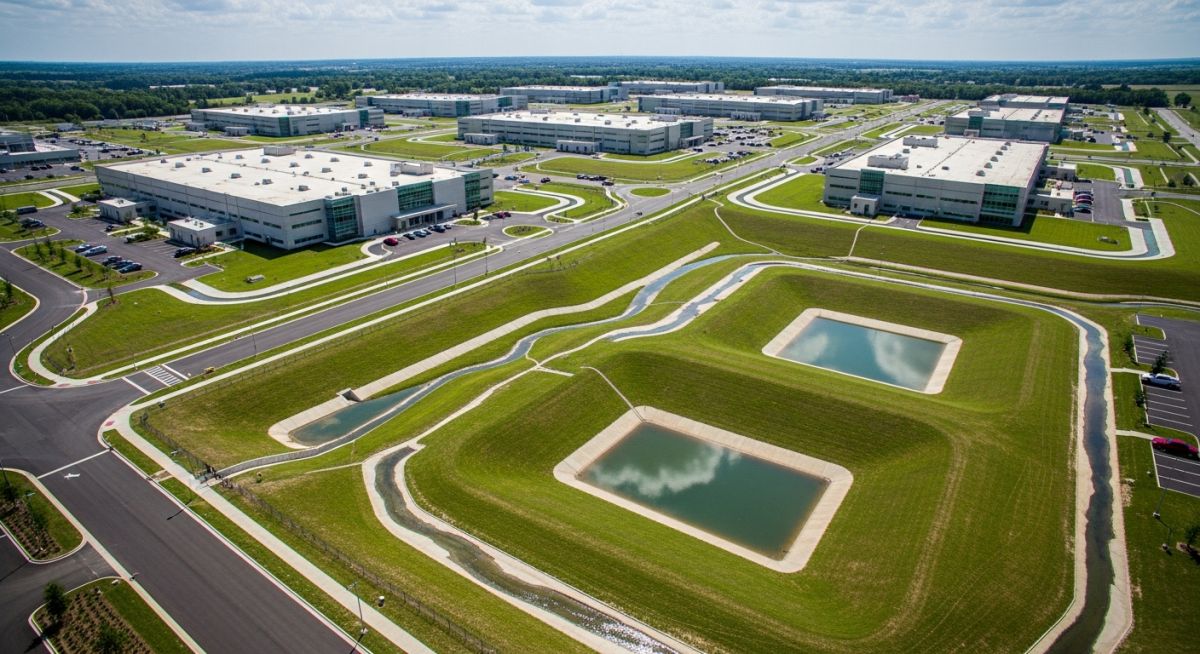
Flood routing is the next critical phase. We model the 100-year, 24-hour storm event to ensure that the finished floor elevation (FFE) remains at least 12 to 24 inches above the calculated base flood elevation (BFE). This vertical buffer is non-negotiable in modern Tier III and Tier IV facility designs. We also incorporate emergency overflow spillways that direct excess water toward designated detention ponds, preventing uncontrolled sheet flow across the site.
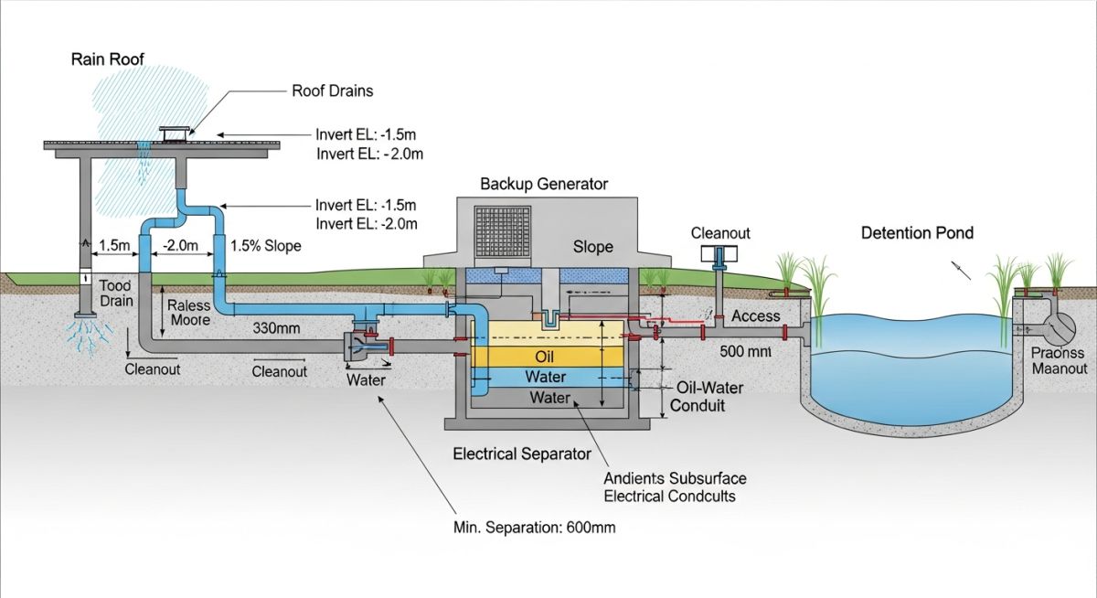
Finally, we must address the interface between the drainage system and the facility’s backup power systems. Fuel storage areas require secondary containment that is hydraulically isolated from the general stormwater network. This prevents potential hydrocarbon contamination from entering the municipal system, which would trigger severe regulatory penalties under Clean Water Act provisions.
Infrastructure Performance Trade-offs: The evaluation of drainage system design choices regarding long-term operational reliability, capital expenditure, and maintenance requirements for mission-critical facilities.
Advantages
- Enhanced site resilience against extreme weather events and flash flooding.
- Reduced risk of foundation settlement caused by uncontrolled groundwater saturation.
- Compliance with stringent environmental discharge permits, avoiding legal liabilities.
- Improved longevity of exterior electrical and mechanical equipment through moisture control.
- Optimized site grading reduces the need for expensive, high-maintenance pumping stations.
Disadvantages
- Higher initial capital expenditure for robust, redundant drainage infrastructure.
- Increased land footprint required for large-scale detention and retention basins.
- Complex regulatory approval processes for site-wide stormwater management plans.
- Ongoing maintenance costs for sediment removal and inspection of oil-water separators.
- Potential for site layout constraints due to mandatory flood routing easements.
Strategic Drainage Implementation: The application of advanced hydraulic engineering solutions across diverse data centre environments to ensure operational continuity and regulatory compliance.
Hyperscale Campus Stormwater Management
Large-scale hyperscale campuses require massive detention volumes to manage the runoff from expansive roof areas and paved parking lots. We utilize underground detention vaults to maximize land utility while ensuring the 100-year storm event is fully contained on-site.
Brownfield Data Centre Redevelopment
Redeveloping existing industrial sites often involves integrating new drainage networks with legacy infrastructure. This requires precise mapping of existing utility lines and the installation of advanced filtration systems to address historical soil contamination concerns during excavation.
High-Density Urban Colocation Facilities
Urban facilities face extreme space constraints, necessitating the use of green roofs and permeable pavement to reduce peak runoff. These systems are integrated with high-capacity vertical drainage stacks that move water efficiently to municipal storm sewers without compromising the building’s structural integrity.
Stormwater Design Parameters and Runoff Coefficients
Stormwater Design Criteria: The systematic application of hydrological modeling and runoff calculations to ensure mission-critical facilities remain operational during extreme weather events.
In my two decades of infrastructure oversight, I have found that the most common failure point in data center civil design is the underestimation of the runoff coefficient (C) for high-density sites. Data centers are unique because they typically feature massive, impervious roof structures and extensive asphalt or concrete loading bays for cooling equipment and generators. This creates a “flash runoff” scenario where the time of concentration is extremely short, putting immediate pressure on the primary drainage network.
When calculating peak discharge using the Rational Method (Q=CiA), we must account for the specific surfacing materials used in modern facilities. While a standard industrial park might use a weighted average, a Tier IV data center requires a conservative approach, often designing for a 100-year or even a 500-year storm event depending on the local ASCE 7 standards. The table below outlines the critical coefficients I use during the preliminary grading and drainage phase to ensure the site can handle peak volumetric flow without surcharging the catch basins.
| Surface Type | Runoff Coefficient (C) | Design Impact for Data Centres | Maintenance Priority |
|---|---|---|---|
| Membrane Roofing | 0.90 – 0.95 | Immediate peak flow; requires high-capacity scuppers. | High: Debris clearing. |
| Asphalt Pavement | 0.70 – 0.95 | Critical for generator yards and fuel delivery paths. | Medium: Crack sealing. |
| Gravel/Crushed Stone | 0.40 – 0.60 | Common in substation areas; provides some infiltration. | Low: Weed control. |
| Landscaped Berms | 0.15 – 0.35 | Used for flood routing and visual screening. | Medium: Erosion control. |
Note: These coefficients are based on saturated soil conditions during extreme precipitation events as per standard civil engineering practice.
Effective Drainage Design Considerations for Data Centres require a multi-layered understanding of how civil infrastructure interacts with mechanical cooling and electrical resilience. This matrix maps the core technical entities involved in site water management to their respective regulatory frameworks and criticality levels. By aligning these components early in the design phase, we prevent the “silo effect” where civil grading conflicts with the placement of outdoor switchgear or cooling towers.
| Technical Entity | Acronym | Primary Standard | Criticality Level |
|---|---|---|---|
| Probable Maximum Precipitation | PMP | NOAA Atlas 14 | Extreme (Tier IV) |
| Best Management Practices | BMP | EPA NPDES | Regulatory Compliance |
| Finished Floor Elevation | FFE | FEMA BFE + 3ft | Life Safety/Asset Protection |
| Oil Water Separator | OWS | API 421 | Environmental Risk |
In my experience, the FFE (Finished Floor Elevation) is the single most important number on a data center site plan. It must be set significantly higher than the Base Flood Elevation (BFE) to account for localized ponding and the potential failure of municipal drainage systems. We typically target a minimum of 3 feet above the 100-year flood level to satisfy both insurance requirements and Uptime Institute Tier III/IV resilience criteria.
Drainage Design Considerations for Data Centres: The rigorous verification of physical site grading, pipe capacities, and emergency overflow paths to prevent water ingress into critical white space.
The transition from design to construction is where most drainage failures originate. I have seen projects where the civil engineer specified a 2% slope away from the building, but the contractor, facing site constraints, reduced it to 0.5%, leading to significant ponding near the air intake louvers. This checklist is designed for site engineers and project managers to use during the “Finished Grading Interface” phase to ensure the theoretical design matches the field reality.
Critical Site Verification Points
-
☐
Positive Grading Verification: Confirm a minimum 2% slope away from the building perimeter for the first 10 feet to prevent foundation saturation. -
☐
Emergency Overflow Paths: Ensure that if catch basins are 100% blocked, the secondary flood route directs water to the detention pond, not the generator yard. -
☐
Backflow Prevention: Verify that all storm lines connected to municipal mains have check valves or backflow preventers to stop city surcharges from entering the site. -
☐
Oil-Water Separator Integrity: Inspect the OWS in the generator refueling area to ensure it is correctly sized for the 10-minute peak rainfall intensity. -
☐
Retention Pond Freeboard: Measure the distance between the 100-year water level and the top of the berm; a minimum of 1 foot of freeboard is required. -
☐
Roof Drainage Clearances: Confirm that downspouts are not discharging directly onto pedestrian walkways or near electrical duct banks.
Beyond the physical checks, documentation is vital. Every data center operator should maintain a “Drainage Maintenance Log” that includes post-storm inspections. If you notice standing water for more than 24 hours in a detention basin, it indicates a failure in the infiltration rate or a blockage in the outlet structure. Addressing these issues during the commissioning phase is significantly cheaper than dealing with a flooded basement during a hurricane.
Field Case Study: Real-World Application
In 2019, I was called to consult on a Tier III data center expansion in a coastal region prone to high-intensity tropical storms. The existing facility had been designed for a 50-year storm, but recent climate data suggested that the 100-year event was now the new baseline. The challenge was to upgrade the drainage capacity without disrupting the 24/7 operations of the existing server halls.
The Problem: Inadequate Flood Routing and Surcharging
The facility faced several critical drainage vulnerabilities during a record-breaking rainfall event:
- The primary storm sewer surcharged, causing water to back up into the loading dock area.
- Finished grading had settled over time, creating a “bowl effect” around the main transformer pad.
- The detention pond reached capacity within 40 minutes, leading to uncontrolled overflow toward the neighbor’s property.
- Debris from the roof membrane blocked 30% of the primary scuppers, increasing the structural load on the roof.
The Outcome: Resilience Through Redundancy
We implemented a multi-stage remediation plan that successfully protected the site during the following hurricane season:
- Installed a redundant, pumped bypass system for the loading dock with a dedicated 500kW backup generator.
- Regraded the transformer yard to provide a 3% slope toward a new bioswale system.
- Expanded the detention pond volume by 40% and added a “smart” outlet control valve to manage discharge rates.
- Implemented a quarterly “Roof-to-River” maintenance program to ensure all flow paths remain clear.
Expert Recommendation: Never rely solely on gravity drainage for critical low points like loading docks or basement pump rooms. Always design for a “consequence of failure” scenario where the municipal system is completely offline. In this case, the addition of the pumped bypass was the difference between a minor nuisance and a multi-million dollar outage.
Frequently Asked Engineering Questions
Why is the 100-year flood event the standard for data centers?
- Tier IV facilities often design for the 500-year event (0.2% probability).
- It ensures that the facility remains accessible for fuel deliveries and emergency personnel during regional disasters.
- Many local jurisdictions now mandate 100-year protection for “Essential Facilities” under the International Building Code (IBC).
How does “Finished Grading” impact server room safety?
- Positive slope (away from the building) prevents hydrostatic pressure on foundation walls.
- It ensures that sheet flow is directed toward catch basins rather than entering air intake louvers located near ground level.
- Proper grading protects underground electrical duct banks from premature corrosion and water ingress.
What is the difference between detention and retention systems?
- Detention is preferred for sites with limited space or where standing water poses a vector (mosquito) risk.
- Retention ponds provide better water quality treatment through biological processes and sedimentation.
- Both are used to meet “Pre-vs-Post” runoff regulations, ensuring the data center doesn’t flood downstream neighbors.
How do we handle “Probable Maximum Precipitation” (PMP)?
- Designing for PMP involves creating “fail-safe” overflow routes that can handle massive volumes without structural damage.
- It often requires the use of large-scale rip-rap channels and emergency spillways in detention basins.
- For data centers, PMP analysis ensures that even in a “biblical” storm, the water has a path to leave the site without entering the building.
Can green roofs be used for data center stormwater management?
- They significantly increase the dead load on the structural steel, which must be accounted for in the seismic design.
- Maintenance access must be strictly controlled to prevent damage to the waterproofing membrane.
- They are highly effective at meeting LEED requirements and reducing the “Urban Heat Island” effect around the facility.
What is the role of backflow prevention in drainage?
- They prevent the city’s stormwater from “backing up” into the data center’s private network.
- Without them, a surcharge in the street could cause water to erupt from the site’s lowest catch basins.
- These valves require annual inspection to ensure that silt or debris hasn’t prevented the flap from sealing correctly.
📚 Recommended Resources: Drainage Design Considerations for Data Centres
Read these Guides
- 📄 Ground Improvement for Data Centres: Engineering Stability and Settlement Control
- 📄 Earthwork Considerations for Data Centres: Site Grading and Foundation Design
- 📄 Flood Risk Assessment for Data Centres: Engineering Design Guide
- 📄 Flood Protection Level Selection for Mission-Critical Data Centre Infrastructure
Complete Course on
Piping Engineering
Check Now
Key Features
- 125+ Hours Content
- 500+ Recorded Lectures
- 20+ Years Exp.
- Lifetime Access
Coverage
- Codes & Standards
- Layouts & Design
- Material Eng.
- Stress Analysis
