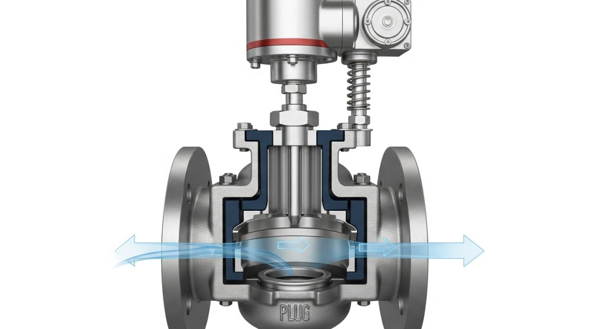
What are Control Valves? | Selection and Types of Control Valves
In my two decades of piping engineering, I have seen countless process upsets traced back to improper valve selection. A control valve is not merely a pipe fitting; it is the “muscle” of your instrumentation loop. When the process controller demands a change, the valve must respond with precision, overcoming static friction and fluid dynamic forces to reach the required setpoint.
Selecting the right valve requires a deep understanding of the fluid properties, pressure drops, and the inherent flow characteristics of the trim. Whether you are dealing with flashing, cavitation, or high-velocity noise, the choice of valve type—be it globe, ball, or butterfly—dictates the stability of your entire plant operation.
Key Takeaways for Engineers:
- Master the Cv and Kv sizing coefficients to prevent undersizing or oversizing.
- Understand the impact of rangeability on low-flow process stability.
- Evaluate cavitation potential using the valve recovery factor (FL).
- Ensure material compatibility with process fluids per ASME B16.34.
Technical Fundamentals of Control Valves
Control Valve Engineering: The systematic application of fluid mechanics and mechanical design to regulate process flow through variable resistance, governed by ISA-75.01 sizing equations.
When I evaluate a control valve, I start with the sizing coefficient (Cv). The Cv represents the flow rate of water in US gallons per minute at 60 degrees Fahrenheit that will pass through a valve with a one-pound-per-square-inch pressure drop. The fundamental sizing equation for non-compressible liquids is Cv = Q multiplied by the square root of (Specific Gravity / Pressure Drop). For gases, the calculation becomes significantly more complex, requiring the inclusion of the expansion factor (Y) and the ratio of specific heats.
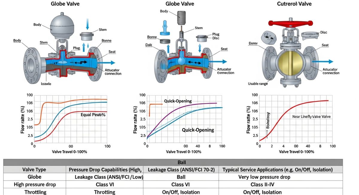
The trim design is the heart of the valve. Linear, equal percentage, and quick-opening characteristics define how the flow changes relative to the valve travel. In my experience, equal percentage trim is the industry standard for most flow control loops because it compensates for the non-linear pressure drop characteristics of the piping system. If you ignore the system resistance curve, you risk “valve hunting,” where the controller cannot find a stable position.
Field Warning: Cavitation and Flashing
Cavitation occurs when the local pressure drops below the vapor pressure of the liquid and then recovers, causing vapor bubbles to collapse against the valve trim. This leads to severe erosion and noise. Always calculate the cavitation index and compare it against the valve recovery factor (FL). If the calculated pressure drop exceeds the allowable limit, you must specify anti-cavitation trim or a multi-stage pressure reduction valve to protect the integrity of the piping system.
Mechanical integrity is governed by ASME B16.34 for pressure-temperature ratings. When selecting the body material, consider not just the pressure, but the potential for corrosion and erosion. For high-pressure drops, I often specify Stellite-faced trim to extend the service life of the plug and seat. Furthermore, the actuator must be sized to provide sufficient thrust to overcome the maximum unbalanced force acting on the valve plug at the worst-case process condition, including the shut-off pressure.
Valve Performance Trade-offs: A critical assessment of mechanical design limitations versus operational flexibility in high-pressure industrial piping environments.
Advantages
- Precise flow modulation across wide ranges.
- High shut-off capability with soft-seat options.
- Customizable trim for specific process noise reduction.
- Excellent compatibility with smart digital positioners.
- Standardized face-to-face dimensions per ISA-75.08.
Disadvantages
- High initial capital cost for specialized alloys.
- Susceptibility to cavitation in high-pressure drops.
- Complex maintenance requirements for internal trim.
- Significant pressure loss compared to full-bore valves.
- Potential for stem packing leaks in toxic service.
Industrial Flow Regulation: Strategic deployment of control valves across diverse process sectors to ensure safety, efficiency, and regulatory compliance.
High-Pressure Steam Letdown
In power generation, globe-style control valves are essential for reducing high-pressure boiler steam to process levels. These valves utilize multi-stage labyrinth trim to dissipate energy, preventing the sonic velocity and vibration that would otherwise destroy downstream piping components.
Chemical Reactor Feed Control
Precise stoichiometry in chemical reactors requires exact flow control of liquid feedstocks. Using equal-percentage trim valves allows the control system to maintain stable reactant ratios even when upstream supply pressures fluctuate, ensuring consistent product quality and preventing thermal runaways.
Cryogenic Liquefied Gas Handling
In LNG facilities, control valves must operate at extreme sub-zero temperatures without seizing. These applications require extended bonnet designs to protect the packing and actuator from freezing, ensuring reliable modulation of cryogenic fluids during loading and storage operations.
Selecting the correct control valve requires a rigorous evaluation of process fluid characteristics, pressure drop requirements, and the desired flow control rangeability. In my two decades of field experience, I have observed that engineers often overlook the interaction between the valve trim geometry and the fluid’s physical state, leading to premature cavitation or flashing. The table below outlines the critical selection criteria that must be cross-referenced against ISA-75.01 standards for flow capacity and ASME B16.34 for pressure-temperature ratings.
When reviewing these parameters, ensure that your Cv calculations account for the worst-case scenario, typically defined by the maximum flow rate at the minimum available pressure drop. Failure to account for these boundary conditions often results in an oversized valve, which leads to poor control loop stability and excessive seat wear due to constant throttling near the closed position.
| Valve Type | Typical Rangeability | Flow Characteristic | Primary Application |
|---|---|---|---|
| Globe Valve | 50:1 | Equal Percentage | High-pressure throttling |
| Ball Valve | 100:1 | Modified Linear | On-off or high-flow |
| Butterfly Valve | 30:1 | Linear | Low-pressure large diameter |
Always verify that the selected actuator torque matches the valve’s breakout torque requirements under maximum differential pressure. A common mistake is selecting an actuator based on nominal operating pressure, ignoring the dynamic forces present during emergency shutdown or process upsets.
The following matrix maps the essential technical entities required for specifying control valves in complex piping networks. By aligning these parameters with international standards, you ensure that the procurement process remains consistent with the project’s safety integrity level (SIL) requirements and long-term maintenance strategies.
Each entity listed below represents a critical node in the control loop. Understanding the relationship between the valve body material, the trim design, and the actuator type is fundamental to preventing common failure modes such as stem packing leaks or seat erosion. Refer to API 6D and NACE MR0175 for material compatibility in sour service environments.
| Entity | Standard Reference | Key Parameter |
|---|---|---|
| Valve Body | ASME B16.34 | Pressure Class |
| Trim Material | NACE MR0175 | Hardness (HRC) |
| Actuator | ISA-75.13 | Torque/Thrust |
This matrix serves as a baseline for your technical data sheets. When filling out these specifications, prioritize the “Key Parameter” column to ensure that the vendor provides equipment that meets the specific process demands of your facility.
Before commissioning any control valve, a systematic site verification is mandatory to prevent operational hazards. In my experience, most field failures stem from improper installation orientation or failure to verify the actuator’s fail-safe position relative to the process safety requirements. Use this checklist to ensure your installation meets the design intent and safety standards.
-
Orientation Check: Verify the flow arrow on the valve body matches the actual process flow direction. -
Fail-Safe Verification: Confirm the actuator fails to the correct position (Open/Closed/Last) per the P&ID. -
Clearance Requirements: Ensure sufficient space for maintenance access and actuator removal without piping disassembly. -
Signal Calibration: Validate the 4-20mA signal range corresponds to the full valve travel (0-100%). -
Leak Testing: Perform a hydrostatic test per ASME B31.3 after installation.
Document every step of this verification process in your commissioning log. If the valve exhibits hunting or oscillation during the initial loop test, check the positioner tuning and ensure the air supply is free of moisture and contaminants. Proper documentation is not just for compliance; it is the primary tool for troubleshooting future performance degradation.
Problem: Severe Cavitation in High-Pressure Let-Down Valve
- Excessive noise and vibration observed in a 4-inch globe valve.
- Rapid degradation of the valve seat and plug within three months of operation.
- Process fluid pressure drop exceeded the critical pressure ratio for the selected trim.
- Incorrect trim selection for the high-velocity liquid service.
Outcome: Successful Mitigation via Multi-Stage Trim Upgrade
- Replaced standard trim with a multi-stage, anti-cavitation trim design.
- Reduced noise levels by 15 decibels, meeting OSHA safety requirements.
- Extended maintenance interval from 3 months to 24 months.
- Achieved stable flow control across the entire operating range.
My recommendation for similar high-pressure applications is to perform a detailed cavitation analysis during the design phase. Do not rely on standard trim for high-pressure drops; always specify anti-cavitation or low-noise trim packages when the pressure drop ratio exceeds 0.5. This proactive approach saves significant operational expenditure over the life of the plant.
What is the difference between linear and equal percentage flow characteristics?
- Linear valves provide a flow rate directly proportional to the stem travel, making them ideal for liquid level control.
- Equal percentage valves provide a flow change that is a constant percentage of the current flow, which is better for pressure control loops.
- Choosing the wrong characteristic often leads to loop instability, where the process variable oscillates around the setpoint.
How do I calculate the required Cv for a control valve?
- Use the standard formula provided in ISA-75.01 for liquid, gas, or steam service.
- Always include a safety factor of 10 to 20 percent above the calculated maximum Cv to ensure the valve is not undersized.
- Verify that the calculated Cv does not exceed the valve’s rated capacity at 100 percent open.
What causes cavitation in control valves and how can it be prevented?
- This phenomenon causes severe erosion of the valve trim and internal body surfaces.
- Prevention involves using multi-stage trim to keep the pressure drop across each stage below the cavitation threshold.
- Alternatively, increasing the downstream pressure or selecting a different valve type can mitigate the risk.
Why is valve rangeability a critical selection factor?
- A high rangeability allows the valve to maintain control across a wide variety of process conditions.
- If the process flow varies significantly, a valve with low rangeability will fail to provide precise control at low flow rates.
- Always match the valve’s rangeability to the expected turndown ratio of your process loop.
What are the advantages of using smart positioners?
- They allow for remote monitoring of valve health, including friction and seat wear analysis.
- Smart positioners can be configured to compensate for non-linearities in the valve’s mechanical response.
- Integration with asset management systems enables predictive maintenance, reducing unplanned downtime.
How do I ensure material compatibility for corrosive fluids?
- Consult NACE MR0175 for sour service and other industry-standard corrosion tables.
- Consider exotic alloys like Hastelloy or Monel for highly aggressive environments where standard stainless steel fails.
- Always verify the compatibility of soft goods like O-rings and gaskets with the process fluid to prevent seal failure.
📚 Recommended Resources: Control Valves
Read these Guides
🎓 Advanced Training



Complete Course on
Piping Engineering
Check Now
Key Features
- 125+ Hours Content
- 500+ Recorded Lectures
- 20+ Years Exp.
- Lifetime Access
Coverage
- Codes & Standards
- Layouts & Design
- Material Eng.
- Stress Analysis
