Table of Contents
How to Prevent Control Valve Cavitation and Flashing Damage
Over my 20 years in piping engineering, I have seen countless control valves destroyed by hydrodynamic forces. I remember a project in a high-pressure water injection system where a standard globe valve was reduced to Swiss cheese in less than two weeks. The culprit? A complete misunderstanding of the pressure profile inside the valve body. When you design process systems, you cannot treat control valves as simple restrictions; they are dynamic thermodynamic environments where liquid can instantly vaporize and collapse with catastrophic energy.
Key Engineering Takeaways
- Understand the pressure recovery profile to predict phase changes.
- Differentiate between cavitation (bubble collapse) and flashing (sustained vapor).
- Utilize multi-stage trim designs to manage pressure drops incrementally.
- Select hardened materials like Stellite 6 or Tungsten Carbide for high-velocity zones.
- Size downstream piping to accommodate two-phase flashing velocities.
Understanding Control Valve Cavitation and Flashing Physics
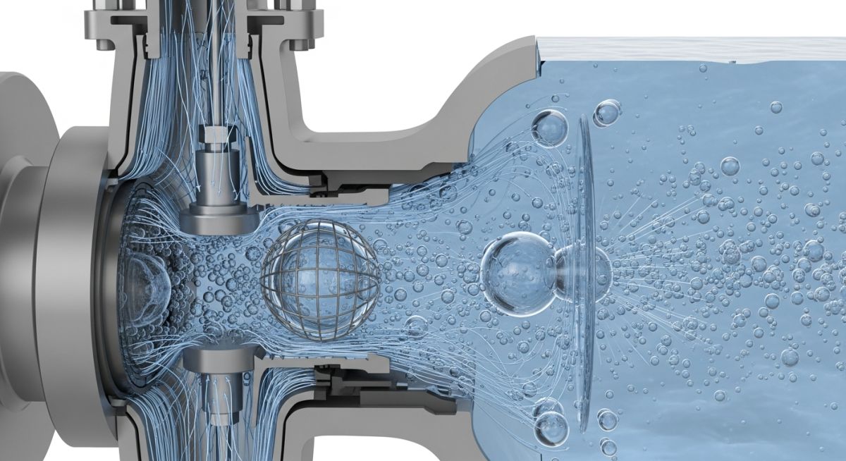
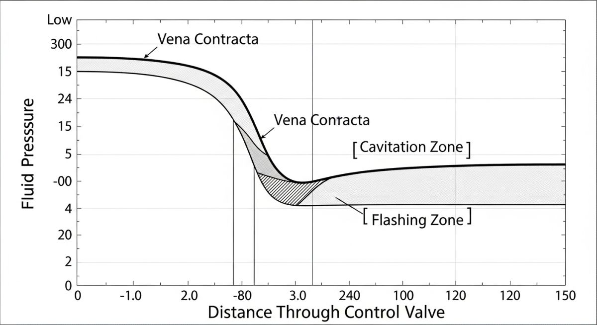
To understand why these phenomena occur, we must look at the pressure profile of a fluid as it passes through a control valve. As the fluid enters the valve restriction (the orifice), the flow area restricts. To maintain mass flow continuity, the fluid velocity must increase. This point of maximum velocity and minimum cross-sectional area is known as the vena contracta.
According to Bernoulli’s principle, this increase in kinetic energy (velocity) comes at the expense of potential energy (static pressure). If the static pressure at the vena contracta drops below the vapor pressure of the liquid at the operating temperature, the liquid begins to boil, forming vapor bubbles.
The Three Stages of Hydrodynamic Flow
Depending on the downstream pressure recovery, the fluid will experience one of three distinct states:
- Choked Flow: This occurs when the pressure drop across the valve is large enough that the velocity at the vena contracta reaches sonic velocity, or when the volume of vapor bubbles limits further mass flow. Beyond this point, decreasing the downstream pressure will not increase the flow rate.
- Cavitation: If the downstream pressure recovers to a level higher than the vapor pressure of the liquid, the vapor bubbles become unstable and collapse violently. This collapse generates localized micro-jets with pressures reaching up to 100,000 psi and temperatures up to 10,000 Kelvin. This mechanical hammering causes micro-fractures, leading to a characteristic “cinder block” or “pitted” appearance on the plug and seat.
- Flashing: If the downstream pressure remains below the vapor pressure of the liquid, the vapor bubbles do not collapse. Instead, they remain as vapor, resulting in a high-velocity, two-phase (liquid-vapor) mixture at the valve outlet. This causes severe erosion, characterized by a smooth, polished, sandblasted appearance on the valve body and downstream piping.
Operating a control valve in choked flow without specialized trim or hardened materials guarantees rapid mechanical failure, severe piping vibration, and structural fatigue of adjacent supports. Always calculate the cavitation index during the design phase.
Mathematical Sizing and Prediction
To predict these phenomena, we use the liquid pressure recovery factor (FL), which is a measure of the valve’s ability to convert kinetic energy back into static pressure. High-recovery valves (like ball and butterfly valves) have low FL values (0.5 to 0.7), making them highly susceptible to cavitation. Low-recovery valves (like globe valves) have high FL values (0.85 to 0.9), making them much more resistant.
The maximum allowable pressure drop for sizing purposes is calculated using the following formula:
Where:
- Delta P_max: Maximum effective pressure drop for sizing (psi or bar)
- FL: Liquid pressure recovery factor (dimensionless)
- P1: Inlet pressure (psia or bar a)
- FF: Liquid critical pressure ratio factor, calculated as: FF = 0.96 – 0.28 * sqrt(Pv / Pc)
- Pv: Vapor pressure of the liquid at inlet temperature (psia or bar a)
- Pc: Thermodynamic critical pressure of the fluid (psia or bar a)
The table below outlines the key differences between choked flow, cavitation, and flashing. Understanding these distinctions is critical for selecting the correct valve geometry and trim materials.
| Parameter | Choked Flow | Cavitation | Flashing |
|---|---|---|---|
| Pressure Profile | P_vc ≤ P_v | P_vc < P_v and P2 > P_v | P_vc < P_v and P2 < P_v |
| Physical State at Outlet | Liquid or Two-Phase | 100% Liquid | Two-Phase (Liquid/Vapor) |
| Damage Mechanism | Flow Limitation / Vibration | Micro-Jet Impact (Pitting) | High-Velocity Erosion (Smooth) |
| Acoustic Signature | High-frequency hiss | Rattling sound (gravel in pipe) | Rushing wind sound |
| Primary Mitigation | Increase valve size / FL | Multi-stage trim / Hardening | Hardened body / Angle valve |
Material selection is your last line of defense when process conditions make it impossible to completely eliminate cavitation or flashing. This matrix maps the recommended materials and trim configurations based on the severity of the service.
| Service Severity | Trim Design | Recommended Materials | Standard Reference |
|---|---|---|---|
| Mild Cavitation (σ > 1.5) | Standard Single-Stage Globe | 316 SST with Stellite 6 Seats | ASME B16.34 |
| Moderate Cavitation (1.0 < σ ≤ 1.5) | Drilled Hole Cage (Single Stage) | Solid Stellite 6 or 440C Martensitic SST | ISA-75.01.01 |
| Severe Cavitation (σ ≤ 1.0) | Multi-Stage Tortuous Path (Labyrinth) | Tungsten Carbide or Hardened Inconel 718 | IEC 60534-8-3 |
| Severe Flashing | Sweep Angle Valve (Flow-to-Open) | Chrome-Moly Body (WC9) with Carbide Trim | API STD 598 |
Mitigating Control Valve Cavitation and Flashing Risks
Before finalizing any control valve specification sheet, you must run through a rigorous verification process. In my field audits, I often find that simple installation errors—like placing a flashing valve too far from the receiver vessel—cause more piping failures than incorrect valve sizing. Use this checklist to verify your design.
Pre-Commissioning & Design Verification Checklist
-
Calculate the Cavitation Index (σ): Ensure the operating index is compared against the valve’s manufacturer-certified damage limit.
-
Verify Valve Orientation: For flashing services, ensure the valve is installed in a “flow-to-open” configuration to prevent high-velocity jet impingement on the stem.
-
Check Downstream Piping Diameter: Verify that downstream piping is expanded immediately after the valve outlet to keep fluid velocities below 150 ft/s (45 m/s) for two-phase flow.
-
Assess Multi-Stage Trim Requirements: If the pressure drop ratio exceeds 0.6, specify a multi-stage trim to split the pressure drop across several chambers.
-
Confirm Hard-Facing Specifications: Ensure all trim components (plug, seat ring, cage) are specified with Stellite 6 or Tungsten Carbide overlay.
Field Case Study: Real-World Application
The Problem: Boiler Feedwater Valve Washout
At a combined-cycle power plant, a 4-inch boiler feedwater control valve was experiencing severe vibration, high-frequency noise (>105 dBA), and complete trim washout within 3 months of operation. The valve was a standard single-stage globe valve operating with an inlet pressure of 1,200 psig and an outlet pressure of 150 psig. The fluid temperature was 280°F. The rapid destruction of the valve plug was causing unscheduled plant shutdowns, costing the operator thousands of dollars per hour.
The Solution & Outcome
I conducted a detailed hydraulic analysis and found that the valve was operating in a state of severe, choked cavitation. The pressure drop of 1,050 psi was far exceeding the valve’s allowable pressure drop limit.
We retrofitted the valve with a multi-stage, tortuous-path labyrinth trim (6 stages of pressure reduction) and upgraded the trim material to solid Tungsten Carbide. This design split the 1,050 psi drop into six smaller steps of approximately 175 psi each, keeping the local pressure at each stage well above the fluid’s vapor pressure.
The results were immediate: noise levels dropped to 76 dBA, piping vibration was completely eliminated, and the valve has now been operating for over four years without a single maintenance intervention.
This case proves that trying to “fight” cavitation with hard materials alone in a single-stage valve is a losing battle. You must design the valve trim to prevent the pressure from dropping below the vapor pressure in the first place.
Frequently Asked Engineering Questions
What is the difference between cavitation and flashing?
How does choked flow limit control valve capacity?
What is the role of the liquid pressure recovery factor (FL)?
Can flashing be completely eliminated in a control valve?
What are the best trim designs for severe cavitation?
How does downstream piping design affect flashing valves?
===
Complete Course on
Piping Engineering
Check Now
Key Features
- 125+ Hours Content
- 500+ Recorded Lectures
- 20+ Years Exp.
- Lifetime Access
Coverage
- Codes & Standards
- Layouts & Design
- Material Eng.
- Stress Analysis

📚 Recommended Resources: control valve cavitation and flashing
Read these Guides


Related posts:
![Professional land surveyor using a total station for a topographic survey in an open field]()
Understanding Land Mapping and the True Topographic Survey Cost
![Side-by-side comparison of an industrial centrifugal pump and a rotary screw compressor.]()
What is the Difference Between Pump and Compressor Systems?
![Cutaway 3D render of an industrial air-operated double-diaphragm pump showing internal components.]()
Understanding Diaphragm Pumps: A Comprehensive Guide for Industrial Plants
![A metallic pipe sleeve embedded in a concrete wall with a carrier pipe passing through it.]()
What is a Pipe Sleeve and How Does It Protect Piping?
![Industrial stainless steel swing check valve installed in a pipeline with a flow direction arrow.]()
What are Check Valves? Types of Check Valves & Their Symbols
![Side-by-side comparison of ASME Section VIII Division 1 and Division 2 pressure vessels with technical blueprints.]()
Understanding the Difference Between ASME Sec VIII Div 1 vs Div 2