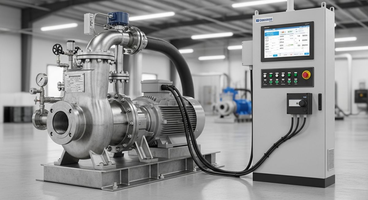
How Centrifugal Pumps with Speed Control Optimize Industrial Piping Systems
In my 20-plus years of designing and commissioning industrial piping networks, I have seen millions of dollars literally burned away by control valves. Engineers often design systems for worst-case scenarios, then use control valves to choke back the flow during normal operations. This throttling is the hydraulic equivalent of driving a car with the accelerator fully depressed while regulating speed using the handbrake.
When we integrate speed control into centrifugal pumping systems, we shift the paradigm. Instead of adding artificial resistance to the system, we directly modify the pump performance curve. In this comprehensive guide, I will share my field-tested insights on how to design, calculate, and verify these systems to achieve maximum reliability and energy savings.
Key Engineering Takeaways
- Understand how the pump affinity laws dictate power savings when reducing rotational speed.
- Identify the critical limits of static head that restrict the minimum operating speed of your pump.
- Learn to protect your pump from low-flow thermal damage and shaft grounding issues.
- Implement a robust pre-commissioning checklist to ensure long-term mechanical integrity.
- Analyze real-world field data showing a 42% reduction in energy consumption.
Why Centrifugal Pumps with Speed Control Save Energy
Variable Speed Energy Conservation: Dynamic speed regulation of centrifugal pumps aligns hydraulic output directly with process demand to eliminate throttling losses in compliance with ASME B73.1 standards. This operational strategy reduces power consumption by utilizing the cubic relationship between pump speed and shaft horsepower.
Understanding the Hydraulic Affinity Laws
Pump Affinity Laws: Mathematical scaling relationships define how changes in impeller rotational speed affect flow rate, differential head, and brake horsepower in centrifugal pumps. These equations provide the theoretical foundation for predicting energy savings when operating under variable frequency drive control.
To understand why speed control is so effective, we must look at the pump affinity laws. These laws describe the relationship between pump speed (N), flow rate (Q), head (H), and shaft power (P). When the impeller diameter remains constant, the relationships are as follows:
The cubic relationship for power is where the massive energy savings come from. If you reduce the pump speed by only 20% (operating at 80% speed), the flow rate drops to 80%, the head drops to 64%, but the power consumption drops to 51.2% of the original value. This is a near 50% reduction in energy consumption for a 20% reduction in speed.
The Impact of Static Head on Speed Regulation
Static Head Limitations: High static head systems restrict the minimum operating speed of variable speed pumps due to the risk of low-flow thermal accumulation and back-flow. Engineers must evaluate the system curve to ensure the pump does not operate below its minimum continuous stable flow limit.
In my experience, many young engineers make the mistake of applying affinity laws without looking at the system curve. A system curve consists of two components: static head (elevation change and vessel pressure) and friction head (losses in pipes, fittings, and valves).
If a system is 100% friction head, the system curve starts at zero head at zero flow. In this ideal scenario, the pump speed can be turned down almost to zero, and the operating point will track the best efficiency point (BEP) perfectly.
However, if the system has high static head (for example, pumping to a pressurized reactor or a high-elevation tank), the system curve starts at a high static head value. If you reduce the pump speed too much, the pump head will fall below the static head of the system. The pump will back-flow, vibrate violently, and overheat. This is why we must always plot the variable speed pump curves against the specific system curve.
Never allow a speed-controlled pump to run below its MCSF for extended periods. At low speeds, the heat generated by the motor and hydraulic friction cannot be dissipated by the low flow rate. This leads to flashing of the process fluid, cavitation, and rapid mechanical seal failure. Always program a minimum speed limit in the variable frequency drive (VFD) to maintain flow above the MCSF specified by the manufacturer under API 610 guidelines.
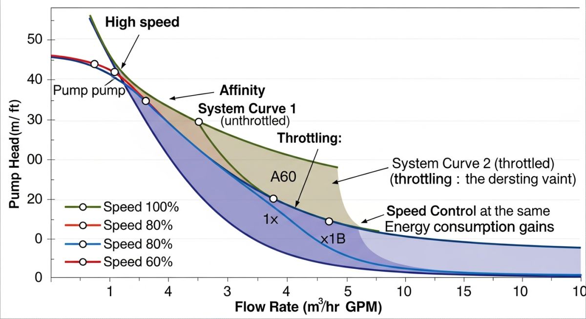
The table below illustrates the theoretical performance of a centrifugal pump complying with ASME B73.1 as speed is reduced, assuming a friction-dominated system.
| Motor Frequency (Hz) | Pump Speed (%) | Relative Flow (%) | Relative Head (%) | Relative Power (%) | Theoretical Energy Saving (%) |
|---|---|---|---|---|---|
| 60.0 | 100% | 100% | 100% | 100% | 0% (Baseline) |
| 54.0 | 90% | 90% | 81% | 73% | 27% |
| 48.0 | 80% | 80% | 64% | 51% | 49% |
| 42.0 | 70% | 70% | 49% | 34% | 66% |
| 36.0 | 60% | 60% | 36% | 22% | 78% |
This matrix maps the critical engineering parameters, acronyms, and standard references required when designing centrifugal pumps with speed control.
| Parameter / Entity | Acronym | Physical Significance | Applicable Standard Reference |
|---|---|---|---|
| Variable Frequency Drive | VFD | Regulates motor speed by adjusting input frequency and voltage. | NEMA ICS 7.1 |
| Minimum Continuous Stable Flow | MCSF | Lowest flow rate at which the pump can operate without damage. | API 610 Clause 6.1.12 |
| Best Efficiency Point | BEP | The point on the pump curve where hydraulic efficiency is maximized. | ASME B73.1 / HI 14.3 |
| Net Positive Suction Head Required | NPSHr | Suction pressure required to prevent cavitation at a given speed. | HI 9.6.1 |
| Electrical Discharge Machining | EDM | Bearing damage caused by induced shaft currents from VFD switching. | NEMA MG 1 Part 31 |
How to Verify Centrifugal Pumps with Speed Control
Pre-Commissioning Verification Protocol: Systematic field inspection of variable speed pumping systems ensures electrical, mechanical, and hydraulic alignment prior to active process operations. This quality control procedure verifies compliance with API 686 installation standards and prevents premature component failure.
Before you press the start button on a newly installed speed-controlled pump, you must perform a series of rigorous field checks. Skipping these steps can lead to catastrophic motor or bearing failures within the first few hours of operation.
Field Verification Checklist
-
Motor Insulation & VFD Duty Rating
Verify that the motor is rated for inverter duty in compliance with NEMA MG 1 Part 31. Standard motors will fail rapidly due to insulation breakdown from high-voltage spikes. -
Shaft Grounding Ring Installation
Confirm that a shaft grounding ring or carbon brush is installed on the motor shaft. This prevents EDM currents from pitting the motor bearings. -
VFD Minimum Speed Parameter Lock
Ensure the VFD minimum frequency is programmed to prevent the pump from running below its MCSF. This value must be calculated based on the system static head. -
Critical Speed Skip Frequencies
Perform a vibration sweep across the entire speed range. Program skip frequencies in the VFD to bypass any structural or rotor resonant frequencies identified during testing. -
External Cooling Fan Verification
If the motor is running at very low speeds (below 30% of nominal), verify that an independent, constant-speed external cooling fan (force-ventilated) is operational.
Field Case Study: Real-World Application
Industrial Retrofit Case Study: Field implementation of variable speed control on a high-vibration cooling water system demonstrates the practical application of API 610 design principles. This real-world analysis highlights the mechanical and financial benefits of replacing control valve throttling with speed regulation.
The Problem: Severe Throttling & High Vibration
At a petrochemical plant in Texas, a large cooling water circulation pump (designed to API 610 standards) was operating with a control valve throttled to 45% open during winter months. This throttling created a massive pressure drop across the valve, wasting approximately 120 kW of continuous electrical power.
Worse, the high differential pressure across the control valve caused severe cavitation within the valve body, leading to excessive piping vibration (exceeding 12 mm/s RMS) and premature mechanical seal failures on the pump every six months.
The Solution: VFD Retrofit & Speed Control
I recommended retrofitting the pump motor with a medium-voltage variable frequency drive (VFD) and fully opening the control valve. We programmed the VFD to receive a feedback signal from the process temperature transmitter, adjusting the pump speed to maintain the target cooling water temperature.
During winter, the pump speed was reduced to 72% of nominal. This matched the process demand perfectly without any throttling.
The Outcome & Financial Return
- Energy Savings: Power consumption dropped from 280 kW to 162 kW, representing a 42% reduction in energy use.
- Vibration Reduction: Piping vibration dropped from 12 mm/s to a highly stable 1.8 mm/s, well within HI 9.6.4 limits.
- Maintenance Savings: Mechanical seal life extended from 6 months to over 4 years, eliminating costly emergency shutdowns.
- Payback Period: The entire project capital expenditure was fully recovered in 14 months through energy savings alone.
My direct recommendation: Always evaluate the payback period of a VFD retrofit for any pump operating with a control valve throttled below 70% for more than 30% of its annual operating hours.
Frequently Asked Engineering Questions
Variable Speed Pump FAQ: Technical reference guide addresses common engineering queries regarding the design, installation, and operation of speed-controlled centrifugal pumps. These answers align with industry standards from the Hydraulic Institute and ASME.
What is the minimum speed limit for centrifugal pumps with speed control?
How does speed control affect the NPSHr of a centrifugal pump?
Can speed control prevent pump cavitation entirely?
What are the main differences between API 610 and ASME B73.1 regarding speed control?
How do you handle high static head systems with variable speed drives?
What electrical considerations are required for VFD motor protection?
Complete Course on
Piping Engineering
Check Now
Key Features
- 125+ Hours Content
- 500+ Recorded Lectures
- 20+ Years Exp.
- Lifetime Access
Coverage
- Codes & Standards
- Layouts & Design
- Material Eng.
- Stress Analysis

📚 Recommended Resources: Centrifugal Pumps with Speed Control
Read these Guides
- 📄 Guide to Types of Pumps and Their Working Principles
- 📄 Centrifugal Compressors: Engineering Design Guidelines and Industrial Applications
- 📄 Understanding Centrifugal Pumps Working and Types for Industrial Plants
- 📄 Electrical Submersible Pumps: Working Principle, Components, and Industrial Applications
