Table of Contents

Mastering Centrifugal Compressor Piping Design and Key Appurtenances
In my 20 years of designing piping systems for global petrochemical plants, I have seen many compressors fail not because of internal machine defects, but due to poorly designed external piping. Centrifugal compressors are highly sensitive machines. They do not tolerate turbulent flow, liquid slugging, or excessive nozzle loads. When you design these systems, you are not just routing pipe; you are protecting a multi-million dollar asset from catastrophic surge, vibration, and mechanical fatigue.
- Master the exact straight-run requirements for suction lines to prevent impeller damage.
- Understand the critical role of eccentric flat-on-top reducers in preventing liquid carryover.
- Learn how to manage nozzle loads to keep your compressor running within API 617 limits.
Centrifugal Compressor Piping Design for Suction Systems
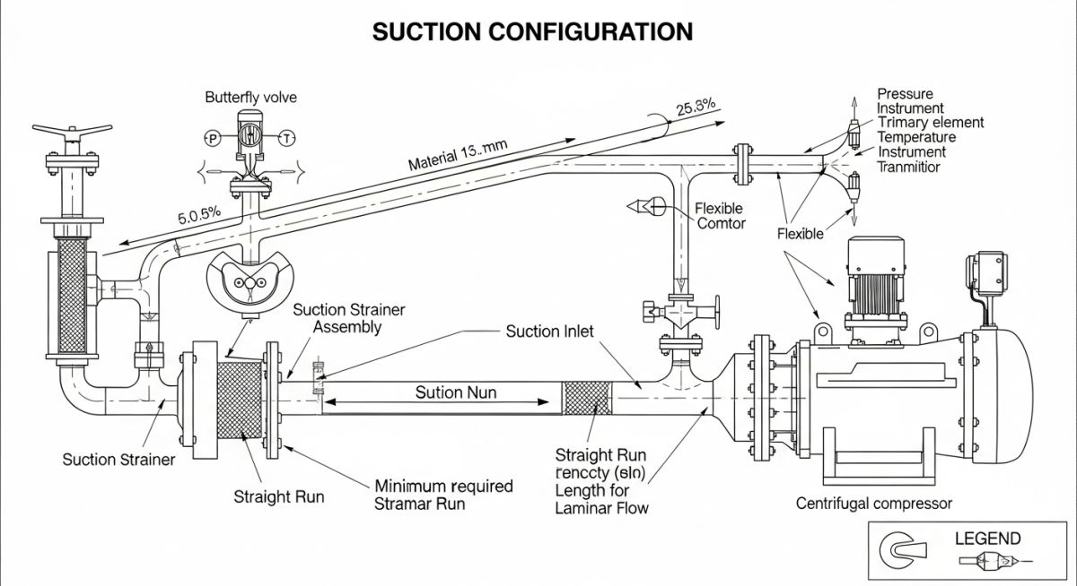
Compressor Suction Piping: This system delivers process gas to the compressor inlet nozzle with uniform velocity profile and zero liquid entrainment in compliance with API 617 standards.
Process Considerations for Suction Piping Design
Process Suction Parameters: These design criteria establish the pressure drop limits and phase behavior controls required to prevent cavitation or liquid carryover into the compressor impeller.
From a process standpoint, the suction line must minimize pressure drop. Every fraction of a bar lost in the suction line directly reduces the compressor’s efficiency and increases power consumption. I always design the suction line to be as direct as possible from the suction knockout drum (KOD) to the compressor nozzle. The gas leaving the KOD must remain superheated; any condensation in the suction line will lead to liquid droplets hitting the high-speed impeller blades, causing severe erosion and dynamic imbalance.
Piping Considerations for Suction Piping Design
Piping Layout Rules: These physical routing constraints dictate the spatial orientation, support locations, and component spacing necessary to minimize flow turbulence and mechanical stress.
1. Straight Length Requirement
To ensure a uniform, non-turbulent velocity profile entering the compressor, a straight run of pipe is mandatory directly upstream of the suction nozzle. In my practice, I enforce a minimum straight length of 10 times the nominal pipe diameter (10D). If the upstream piping contains out-of-plane elbows or throttling valves, this requirement can extend to 15D or even 20D. Without this straight run, the gas will enter the impeller with a swirling motion, causing asymmetric loading, high-frequency vibration, and premature bearing failure.
2. Slope of Compressor Suction Piping
All horizontal runs of suction piping must slope continuously back toward the suction knockout drum. A minimum slope of 1:100 is standard. This ensures that any liquid that condenses during shutdown or low-flow conditions drains back to the vessel rather than pooling in the pipe. Pocketing in the suction line is a critical design error that must be avoided at all costs.
3. Suction Strainer
During commissioning and initial startup, construction debris such as welding slag, dirt, and tools can easily destroy the compressor internals. A temporary conical (witch’s hat) strainer must be installed in the suction line. I locate this strainer in a spool piece close to the compressor, ensuring there is sufficient space for removal. The strainer must be designed to withstand the maximum differential pressure without collapsing.
4. Low Point Drain
If a low point is absolutely unavoidable due to structural constraints, a valved low-point drain must be provided. This drain must be fitted with double isolation valves and a blind flange or plug to prevent accidental leakage of hazardous process gases.
5. Lube & Seal Oil System
The compressor’s bearings and seals require a continuous supply of clean oil. The lube and seal oil piping must be routed carefully to avoid interfering with the main process piping maintenance access. I always specify stainless steel for all lube oil piping downstream of the filters to prevent rust particles from entering the high-precision bearings.
| Upstream Fitting Type | Minimum Straight Run (D) | Recommended Straight Run (D) | Applicable Code / Standard |
|---|---|---|---|
| Single Elbow | 10D | 12D | API 617 |
| Two Elbows (In-Plane) | 12D | 15D | API 617 / ASME B31.3 |
| Two Elbows (Out-of-Plane) | 15D | 20D | API 617 |
| Throttling / Control Valve | 20D | 25D | ASME B31.3 |
| Component Name | Primary Function | Typical Location | Design Standard |
|---|---|---|---|
| Suction Isolation Valve | Isolates compressor for maintenance | Upstream of suction strainer | API 6D |
| Discharge Check Valve | Prevents backflow and reverse rotation | Downstream of discharge nozzle | API 6D / API 594 |
| Blowdown Valve | Depressurizes system during emergency | Connected to flare header | API 520 / API 521 |
| Emergency Shutdown Valve (ESDV) | Rapid isolation of hazardous inventory | Battery limit of compressor station | API 553 / ASME B16.34 |
Site Verification for Compressor Piping
Piping Verification Checklist: This quality assurance protocol verifies that the physical installation matches the stress analysis models and process flow requirements prior to startup.
Before handing over the system to the commissioning team, I perform a rigorous walkdown. Here is the exact checklist I use to verify the integrity of the installation.
-
Verify 10D straight run upstream of the suction nozzle is free of any branch connections or instruments. -
Confirm eccentric reducer on horizontal suction line is installed flat-side-up (FSU). -
Check that the temporary suction strainer is installed with the cone pointing upstream (against the flow). -
Ensure all low-point drains are fitted with double isolation valves and blind flanges. -
Verify spring hangers are in their “cold” pin positions and travel stops are removed before oil flush. -
Confirm the discharge check valve is installed in the correct flow direction and has a dampening mechanism.
Field Case Study: Real-World Application
Optimizing Centrifugal Compressor Piping Design for Discharge Lines
Compressor Discharge Piping: This high-pressure system routes compressed gas safely to downstream units while managing thermal expansion and acoustic pulsation.
Why is a straight run of pipe required before the compressor suction nozzle?
What is the purpose of using an eccentric flat-on-top reducer in suction lines?
How do you handle thermal expansion and nozzle loads on a centrifugal compressor?
What is the role of a blowdown valve in a compressor piping system?
Why is a non-slam check valve preferred on the compressor discharge line?
How does the suction strainer protect the compressor during commissioning?
Complete Course on
Piping Engineering
Check Now
Key Features
- 125+ Hours Content
- 500+ Recorded Lectures
- 20+ Years Exp.
- Lifetime Access
Coverage
- Codes & Standards
- Layouts & Design
- Material Eng.
- Stress Analysis

📚 Recommended Resources: centrifugal compressor piping design
Read these Guides
🎓 Advanced Training


Related posts:
![Aerial view of a modern municipal wastewater treatment plant featuring circular clarifiers and aeration basins.]()
Wastewater Treatment: Process Steps, Design Considerations, and Plant Types
![An offshore crude oil drilling rig operating in the ocean at sunset.]()
Understanding Crude Oil Price and Types for Piping Design
![Steel sucker rod string being installed at an oil well pumpjack site.]()
What is a Sucker Rod? Its Types and Critical Importance
![Cutaway diagram of a fire-safe ball valve showing primary and secondary metal-to-metal seals.]()
What is Fire-Safe Valve? API 607 vs API 6FA
![A maintenance engineer inspecting industrial machinery with a digital diagnostic overlay.]()
Optimizing Plant Reliability with the Core Types of Maintenance
![Industrial vortex flow meter installed on a pipeline with a digital display showing flow rate.]()
What is a Vortex Flow Meter and How Does It Work