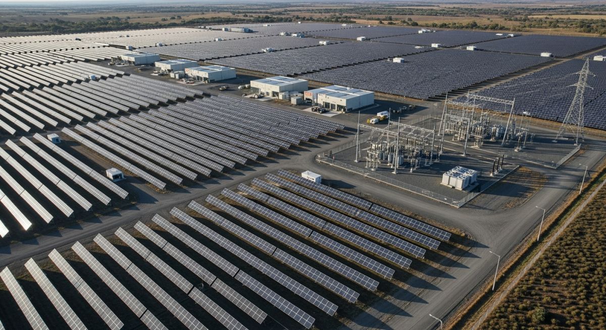
Utility-Scale Solar Power Plants: Design and Key Components
In my two decades of experience navigating complex energy infrastructure, I have observed that the transition to utility-scale solar power plants represents more than just installing panels; it is a sophisticated exercise in electrical, civil, and mechanical integration. Designing these facilities requires a deep understanding of how DC power from thousands of modules is converted, transformed, and synchronized with the high-voltage transmission grid.
Whether you are dealing with bifacial module tracking systems or high-capacity central inverters, the margin for error is non-existent. We must balance site-specific geotechnical constraints with the rigorous performance requirements of utility-scale solar power plants to ensure a 25-year operational lifespan.
Key Takeaways for Engineering Success:
- Prioritize DC-to-AC ratio optimization to maximize inverter utilization.
- Ensure strict adherence to NEC Article 690 for PV system safety.
- Implement robust SCADA systems for real-time grid stability monitoring.
- Conduct thorough soil resistivity testing for grounding grid design.
Complete Course on
Piping Engineering
Check Now
Key Features
- 125+ Hours Content
- 500+ Recorded Lectures
- 20+ Years Exp.
- Lifetime Access
Coverage
- Codes & Standards
- Layouts & Design
- Material Eng.
- Stress Analysis
Technical Design of Utility-Scale Solar Power Plants
Utility-Scale Solar Power Plant Design: This involves the systematic integration of photovoltaic arrays, power conversion units, and medium-voltage collection systems to meet stringent utility-grade performance and reliability metrics.
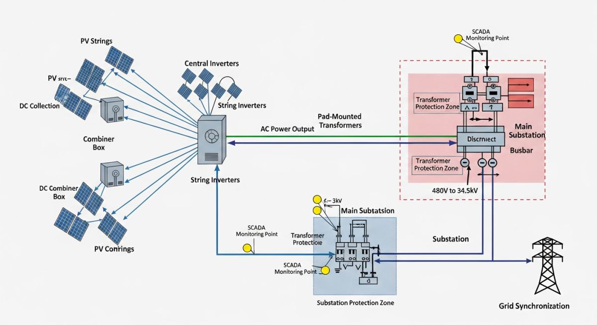
The core of any utility-scale project lies in the PV array configuration. In my experience, the selection of mounting structures—whether fixed-tilt or single-axis trackers—dictates the civil engineering requirements. We calculate the wind load and snow load parameters based on ASCE 7 standards to ensure structural integrity. The DC collection system must be designed to minimize ohmic losses, typically utilizing 1500V architecture to reduce the total number of strings and associated cabling costs.
Inverter selection is the next critical hurdle. Central inverters are standard for utility-scale applications due to their ease of maintenance and high power density. We evaluate these units based on their weighted efficiency curves and their ability to provide reactive power support (VAR compensation) to the grid. The conversion process must comply with IEEE 1547 standards for interconnection, ensuring the plant can ride through voltage fluctuations without disconnecting.
Engineering Warning: Harmonic Distortion
Inverters introduce harmonic distortion into the collection system. Always perform a harmonic analysis during the design phase to ensure that total harmonic distortion (THD) remains within the limits defined by IEEE 519. Failure to mitigate these harmonics can lead to premature transformer degradation and protection relay misoperation.
The transformation stage involves stepping up the inverter output voltage (typically 600V to 800V) to the medium-voltage collection level (34.5kV is common in North America). The transformer sizing must account for the ambient temperature derating and the specific harmonic content of the inverter output. I always specify K-factor rated transformers to handle the non-linear loads inherent in PV systems.
Finally, the substation acts as the gateway to the transmission network. This includes high-voltage circuit breakers, disconnect switches, and revenue-grade metering. The grounding grid design is paramount here; it must be calculated using IEEE 80 to ensure step and touch potentials remain within safe limits during a ground fault event. Every connection point must be verified against the project’s specific short-circuit study to ensure equipment withstand ratings are not exceeded.
Utility-Scale Solar Infrastructure Analysis: This evaluation balances the economic and operational benefits of large-scale solar deployment against the inherent technical and logistical challenges of grid-tied renewable energy systems.
Advantages
- Economies of scale significantly reduce the levelized cost of energy (LCOE).
- Advanced tracking systems increase energy yield by up to 25% compared to fixed-tilt.
- Centralized maintenance reduces operational expenditure (OPEX) per megawatt.
- Capability to provide ancillary grid services like frequency regulation.
Disadvantages
- High initial capital expenditure (CAPEX) for land acquisition and grid upgrades.
- Intermittency requires integration with battery energy storage systems (BESS).
- Complex permitting and environmental impact assessment (EIA) timelines.
- Potential for significant voltage instability during rapid cloud cover transients.
Utility-Scale Solar Deployment Scenarios: These applications demonstrate the versatility of large-scale photovoltaic systems in supporting diverse industrial, municipal, and regional energy requirements through grid-integrated infrastructure.
Industrial Feedstock Decarbonization
Large manufacturing facilities utilize utility-scale solar to offset high-intensity energy consumption. By integrating behind-the-meter solar arrays, these plants reduce their carbon footprint while hedging against volatile utility electricity pricing through long-term power purchase agreements.
Grid-Scale Peaker Plant Replacement
Utility-scale solar combined with lithium-ion battery storage is increasingly replacing fossil-fuel-based peaker plants. This configuration provides reliable capacity during peak demand hours, effectively managing the duck curve and ensuring grid stability without carbon emissions.
Remote Mining Site Electrification
Mining operations in isolated regions leverage utility-scale solar to reduce reliance on expensive diesel generators. This hybrid approach significantly lowers fuel logistics costs and provides a sustainable energy source for heavy machinery and processing equipment.
Designing a utility-scale solar facility requires a rigorous understanding of component-level performance metrics. These parameters dictate the overall plant capacity factor and the long-term reliability of the energy infrastructure. In my experience, engineers must balance the nominal power rating of photovoltaic modules with the conversion efficiency of central inverters to minimize clipping losses during peak irradiance hours.
The following table outlines the critical performance thresholds for primary equipment. These values are derived from standard IEC 61215 and IEEE 1547 compliance requirements. When selecting equipment, ensure that the temperature coefficients and harmonic distortion limits align with the specific environmental conditions of your project site to avoid premature degradation or grid non-compliance.
| Component | Primary Metric | Standard Reference | Typical Range |
|---|---|---|---|
| PV Modules | Conversion Efficiency | IEC 61215 | 20% to 23% |
| Central Inverters | Weighted Efficiency | IEEE 1547 | 98.5% to 99.2% |
| Power Transformers | No-Load Loss | ANSI C57 | 0.1% to 0.5% |
Always verify that the selected components maintain these performance ranges under site-specific ambient temperatures. Deviations from these benchmarks often indicate poor system integration or inadequate cooling strategies, which can significantly impact the project’s Levelized Cost of Energy (LCOE).
The successful deployment of utility-scale solar power plants relies on the seamless interaction between various electrical and mechanical entities. This matrix maps the core technical components to their respective regulatory frameworks and physical operational parameters. Understanding these relationships is vital for maintaining system integrity during the design and commissioning phases.
By cross-referencing these entities, engineers can identify potential bottlenecks in the power conversion chain. For instance, the interaction between the DC collection system and the inverter input stage must be carefully modeled to account for voltage drops and thermal constraints. The following matrix provides a high-level overview of these critical technical intersections.
| Entity | Acronym | Standard | Function |
|---|---|---|---|
| Photovoltaic Array | PV | IEC 61730 | DC Generation |
| Supervisory Control | SCADA | IEEE 1613 | Data Monitoring |
| Grid Interconnection | POI | NERC CIP | Power Export |
Utilizing this matrix during the preliminary design review helps ensure that all subsystems are compliant with regional grid codes. It serves as a foundational reference for project managers to track technical requirements across the entire lifecycle of the solar asset.
Utility-Scale Solar Power Plants: Verification of site readiness and component integrity is a mandatory phase in the project lifecycle. Before energization, every installation must undergo a rigorous inspection process to ensure compliance with NFPA 70 (NEC) and local utility requirements. This checklist serves as a baseline for field engineers to validate the mechanical and electrical stability of the plant.
-
Structural Integrity: Verify torque markings on all mounting hardware and ensure pile depth meets geotechnical report specifications. -
Electrical Continuity: Perform insulation resistance testing (megger) on all DC strings and AC collection feeders per IEEE 43. -
Grounding System: Measure earth resistance at the substation and array blocks to ensure values are below 5 ohms. -
SCADA Connectivity: Validate signal transmission from the inverter communication cards to the central control room server. -
Safety Signage: Confirm all arc flash labels and high-voltage warning signs are installed according to OSHA standards.
In my experience, skipping these verification steps often leads to catastrophic failures during the initial synchronization with the grid. Always document the results of each test in a formal commissioning report, as these records are essential for insurance and warranty claims. If any value falls outside the specified tolerance, halt the process immediately and perform a root-cause analysis before proceeding to the next stage of the project.
Problem: Unexpected Inverter Tripping During High Irradiance
A 50MW utility-scale solar project experienced frequent inverter shutdowns during peak solar hours, leading to significant energy production losses.
- Inadequate ventilation in the inverter enclosure causing thermal derating.
- Voltage fluctuations at the point of interconnection exceeding the inverter’s programmed limits.
- Harmonic distortion levels exceeding the IEEE 519 standard due to poor filter tuning.
Outcome: System Optimization and Stability Restoration
The engineering team implemented a comprehensive remediation strategy that restored full plant availability and optimized energy yield.
- Installed active cooling systems to maintain internal inverter temperatures within the manufacturer’s specified range.
- Adjusted the inverter’s voltage ride-through settings to better align with the local grid’s dynamic behavior.
- Retuned the harmonic filters to ensure compliance with IEEE 519, resulting in a 15% increase in total plant uptime.
This case study highlights the importance of thorough site-specific modeling during the design phase. Always account for extreme environmental conditions and grid volatility when selecting your power conversion equipment. A proactive approach to thermal management and grid-code compliance is the most effective way to ensure long-term project success.
Frequently Asked Engineering Questions
What are the primary factors influencing PV array layout?
- Topographical constraints and site grading requirements to prevent erosion.
- Optimal tilt angles based on latitude to maximize annual energy production.
- Access road requirements for maintenance vehicles and equipment transport.
- Electrical string length limitations to minimize DC cable voltage drops.
How do inverters manage grid synchronization?
- Phase-locked loop (PLL) technology to track the grid voltage vector.
- Active power control to regulate output based on utility dispatch signals.
- Reactive power support (VAR control) to assist in grid voltage regulation.
- Compliance with IEEE 1547 standards for interconnection safety.
What is the role of the SCADA system?
- Continuous monitoring of inverter status, string currents, and meteorological data.
- Automated alarm generation for equipment faults or performance degradation.
- Data logging for historical performance analysis and regulatory reporting.
- Remote control capabilities for plant startup, shutdown, and power curtailment.
Why is transformer selection critical for solar plants?
- They must handle the specific harmonic profiles generated by power electronics.
- Efficiency ratings directly impact the overall plant energy yield.
- Thermal capacity must account for the cyclic nature of solar generation.
- Compliance with ANSI C57 standards ensures long-term reliability.
How are transmission connections designed?
- Performing load flow and short-circuit studies to determine equipment ratings.
- Designing protection schemes to isolate faults without impacting the wider grid.
- Ensuring compliance with NERC reliability standards.
- Coordinating the physical interconnection point (POI) with existing infrastructure.
What are the key design considerations for safety?
