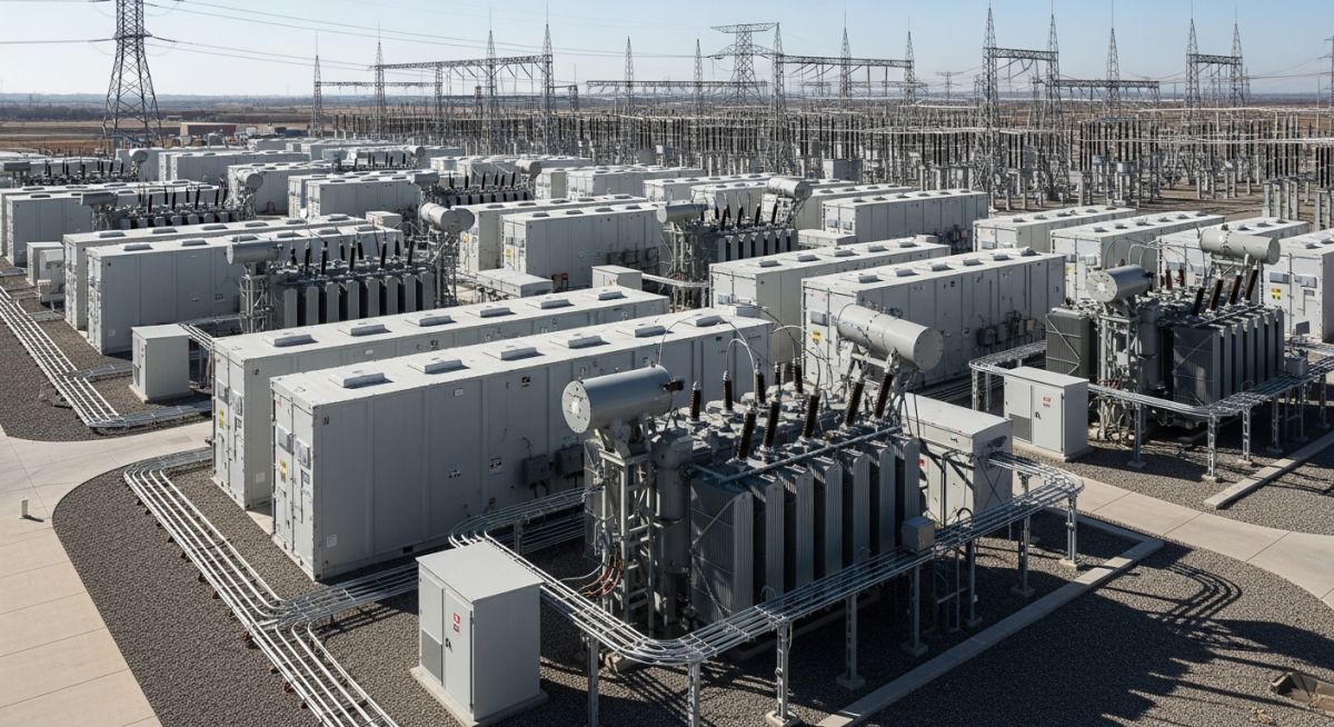
Battery Energy Storage Systems (BESS) Explained: Complete Guide for Engineers
In my two decades of experience navigating complex industrial infrastructure, I have observed few technologies as transformative as modern Battery Energy Storage Systems (BESS). As we pivot toward a decarbonized grid, the inherent intermittency of solar and wind assets necessitates a robust, high-density storage buffer. BESS is no longer just a pilot project; it is the backbone of modern grid reliability.
This guide dissects the engineering architecture, thermal management requirements, and safety protocols essential for deploying utility-scale storage. Whether you are managing site integration or evaluating battery chemistry, understanding the interplay between power conversion systems and electrochemical cells is paramount for project success.
Key Engineering Takeaways:
- Mastering the thermal runaway mitigation strategies required by UL 9540A.
- Optimizing DC-to-AC conversion efficiency through advanced power electronics.
- Navigating site-specific civil and structural requirements for high-density containerized units.
- Implementing effective BMS (Battery Management System) logic for state-of-charge accuracy.
Technical Architecture of Battery Energy Storage Systems
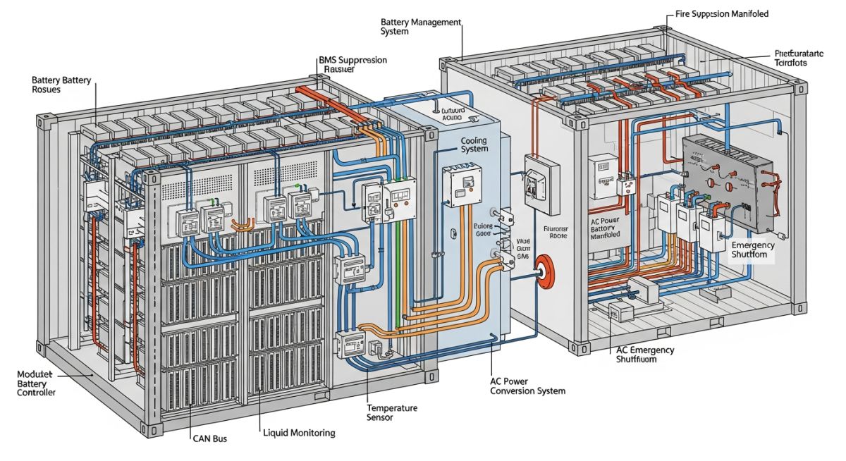
BESS Technical Architecture: A multi-layered engineering framework comprising electrochemical cells, power conversion systems, and sophisticated control logic designed to manage energy flow while maintaining thermal stability under varying load profiles.
At the core of any BESS project lies the battery module, typically utilizing Lithium Iron Phosphate (LFP) or Nickel Manganese Cobalt (NMC) chemistries. From an engineering perspective, the design must account for the C-rate, which defines the discharge speed relative to the maximum capacity. For instance, a 1C rate implies the battery discharges its full capacity in one hour. We must calculate the total energy throughput while considering the Depth of Discharge (DoD) to ensure the system meets its 10-to-20-year operational lifecycle.
Power Conversion and Grid Synchronization
The Power Conversion System (PCS) acts as the bridge between the DC battery bank and the AC grid. It is essentially a bidirectional inverter that must handle reactive power compensation and frequency regulation. In my experience, the most common failure points in BESS are not the cells themselves, but the thermal management systems and the inverter control loops.
Engineering Warning: Thermal Management
Failure to maintain cell temperatures within the optimal range (typically 15 to 35 degrees Celsius) leads to accelerated degradation and increased risk of thermal runaway. Always ensure the HVAC or liquid cooling system is sized for the maximum heat rejection rate during peak charge/discharge cycles, accounting for ambient temperature extremes at the site.
When designing the balance of plant, we must adhere to IEC 62619 for safety requirements. The structural design of the container must also account for seismic loading and fire suppression integration. I recommend a modular approach where each container acts as an independent fire zone, utilizing gas-based suppression systems to prevent cascading failures across the entire site.
Finally, the Battery Management System (BMS) is the brain of the operation. It monitors individual cell voltages, temperatures, and current. If the BMS detects a deviation beyond the predefined safety threshold, it must trigger an immediate disconnect via the DC contactors. This logic is critical for maintaining the State of Health (SoH) and ensuring the system remains within the safe operating area (SOA) defined by the manufacturer.
BESS Operational Trade-offs: A critical evaluation of the performance benefits versus the technical and economic constraints inherent in current electrochemical storage deployments.
Engineering Advantages
- Rapid response times (sub-millisecond) for frequency regulation.
- High round-trip efficiency (RTE) often exceeding 90 percent.
- Modular scalability allowing for incremental capacity expansion.
- Reduced reliance on fossil-fuel-based peaker plants.
- Enhanced grid stability through synthetic inertia provision.
Engineering Disadvantages
- Significant fire safety and suppression infrastructure costs.
- Degradation over time requiring periodic cell augmentation.
- Complex thermal management requirements for high-density units.
- Supply chain volatility for critical battery minerals.
- Stringent environmental permitting for large-scale installations.
Industrial BESS Deployment: Strategic implementation of energy storage to solve specific grid-edge challenges and optimize industrial power consumption profiles.
Renewable Energy Time-Shifting
BESS allows operators to capture excess solar or wind generation during low-demand periods and discharge it during peak hours. This effectively flattens the duck curve and prevents curtailment of renewable assets, ensuring maximum ROI for utility-scale solar farms.
Grid Frequency Regulation
By providing fast-acting active power injection, BESS systems help maintain grid frequency within the tight tolerances required by transmission system operators. This application is highly lucrative in markets with ancillary service payments, as the system can respond to frequency deviations in milliseconds.
Industrial Peak Shaving
Large industrial facilities utilize BESS to reduce peak demand charges by discharging stored energy during periods of high facility consumption. This strategy significantly lowers monthly utility bills and reduces the stress on local distribution transformers during peak operational hours.
Microgrid Resilience
In remote or mission-critical environments, BESS provides essential backup power and black-start capabilities. By integrating with local generation, the system ensures continuous operation during grid outages, protecting sensitive industrial processes from costly downtime.
When evaluating Battery Energy Storage Systems (BESS) for utility-scale deployment, engineers must reconcile disparate performance metrics that dictate project viability. The following table outlines the critical operational thresholds for common lithium-ion chemistries, specifically focusing on Nickel Manganese Cobalt (NMC) and Lithium Iron Phosphate (LFP) variants. These parameters are derived from IEEE 2030.2.1 standards, which govern the interface between energy storage and the electric power grid.
It is vital to note that these values represent nominal operating conditions. In practice, environmental factors such as ambient temperature, state-of-charge (SoC) cycling depth, and the efficiency of the Battery Management System (BMS) will significantly influence these figures. Engineers should utilize these data points as a baseline for initial feasibility studies before proceeding to detailed thermal modeling or site-specific load flow analysis.
| Parameter | NMC Chemistry | LFP Chemistry | Unit |
|---|---|---|---|
| Cycle Life (80% DoD) | 2,000 – 3,000 | 5,000 – 8,000 | Cycles |
| Energy Density | 150 – 220 | 90 – 160 | Wh/kg |
| Thermal Stability | Moderate | High | Rating |
| Round-Trip Efficiency | 92 – 95 | 88 – 92 | Percent |
The selection between these chemistries often hinges on the specific application requirements. For high-frequency ancillary services where cycle count is the primary driver of degradation, LFP is frequently preferred due to its superior cycle life. Conversely, space-constrained projects where energy density is the limiting factor may necessitate the use of NMC, provided that the fire suppression and thermal management systems are designed to handle the higher thermal runaway risk.
The successful integration of a BESS into an existing electrical infrastructure requires a deep understanding of the interconnected components and their respective regulatory frameworks. This matrix maps the physical hardware entities to their corresponding engineering standards and primary functional roles within the system architecture. By aligning these components with NFPA 855 and UL 9540, engineers can ensure that the design meets the stringent safety requirements for modern energy storage facilities.
This mapping is intended to serve as a reference for procurement and design verification. Each entity listed plays a distinct role in the conversion, storage, or management of electrical energy, and failure to account for the interaction between these components can lead to system-wide inefficiencies or catastrophic failure modes.
| Entity | Primary Function | Standard Reference |
|---|---|---|
| Battery Module | Energy Storage | UL 1973 |
| PCS (Inverter) | DC to AC Conversion | IEEE 1547 |
| BMS | Cell Monitoring/Safety | IEC 62619 |
| HVAC/TMS | Thermal Regulation | ASHRAE 90.1 |
Engineers should verify that all components are listed or certified under the referenced standards before site installation. The interaction between the Power Conversion System (PCS) and the Battery Management System (BMS) is particularly critical, as the communication protocol latency can directly impact the system’s response time to grid frequency events.
Commissioning a Battery Energy Storage System is a multi-disciplinary effort that demands rigorous adherence to safety protocols and technical specifications. Before the system is energized, the site must undergo a comprehensive verification process to ensure that all electrical, mechanical, and software components are functioning within their design envelopes. This checklist serves as a foundational guide for field engineers to validate the integrity of the installation.
-
[ ]
Grounding Continuity: Verify that all battery enclosures and the PCS chassis are bonded to the site grounding grid per NFPA 70 (NEC) requirements. -
[ ]
Thermal Management Loop: Confirm that the coolant flow rate and pressure in the liquid cooling system meet the manufacturer’s specifications for the expected ambient temperature range. -
[ ]
BMS Communication Latency: Perform a ping test between the BMS master controller and the PCS to ensure communication latency is below the 50ms threshold required for grid frequency regulation. -
[ ]
Fire Suppression Integration: Validate that the fire detection system is hard-wired to the emergency shutdown (ESD) circuit to trigger an immediate isolation of the DC bus upon alarm. -
[ ]
Insulation Resistance: Conduct a megger test on all DC cabling to ensure insulation resistance exceeds the minimum values specified in IEEE 43.
Following these verification steps is not merely a matter of compliance; it is a critical safeguard against the high-energy risks inherent in large-scale battery installations. Any deviation from these parameters during the commissioning phase must be documented, analyzed, and rectified before the system is allowed to synchronize with the utility grid. Always maintain a detailed log of all test results, as these records are essential for future maintenance and warranty claims.
The Problem: Unexpected Thermal Runaway in a 20MW BESS Facility
- Inadequate airflow design led to localized hot spots within the battery container during peak summer ambient temperatures.
- The BMS failed to trigger a power derating command because the temperature sensors were placed too far from the high-resistance busbar connections.
- Coolant pump cavitation occurred due to improper system venting, causing a sudden loss of thermal regulation in one rack.
- The lack of an automated emergency ventilation system allowed heat to accumulate, eventually breaching the cell casing integrity.
The Outcome: Successful Mitigation and System Redesign
- Implemented a redundant, high-capacity liquid cooling loop with real-time flow monitoring at each rack level.
- Relocated temperature sensors to the most critical heat-generating points, specifically the busbar-to-module connection interfaces.
- Updated the BMS firmware to include a predictive thermal model that initiates derating based on the rate of temperature rise rather than absolute thresholds.
- Installed an automated fire suppression system that utilizes clean agent gas to extinguish fires without damaging the remaining healthy modules.
This case highlights the necessity of robust thermal design in BESS projects. My recommendation for future installations is to prioritize thermal redundancy and sensor placement accuracy during the initial design phase. Relying solely on manufacturer-provided cooling configurations is often insufficient for site-specific environmental conditions, and proactive thermal modeling is the only way to ensure long-term system reliability.
How does BESS contribute to grid frequency regulation?
- The PCS monitors the grid frequency and compares it against the nominal 50Hz or 60Hz setpoint.
- When frequency drops, the BESS discharges power to provide synthetic inertia and restore balance.
- When frequency rises, the BESS absorbs excess energy, preventing potential damage to grid-connected equipment.
- This capability is governed by IEEE 1547, which defines the interconnection requirements for distributed energy resources.
What are the primary fire safety standards for BESS?
- NFPA 855 mandates a hazard mitigation analysis to evaluate the risk of thermal runaway and its impact on surrounding structures.
- UL 9540 serves as the primary safety standard for the entire energy storage system, covering both the battery and the PCS.
- UL 9540A is a specific test method used to evaluate the fire propagation characteristics of battery modules when subjected to thermal runaway.
- Engineers must ensure that the fire suppression system is compatible with the specific battery chemistry, as water-based systems may not be effective for certain lithium-ion fires.
How is the state-of-health (SoH) of a BESS calculated?
- Capacity fade is tracked by measuring the total energy throughput over the life of the battery.
- Internal resistance increases as the battery ages, which can be measured during charge/discharge cycles to estimate SoH.
- Advanced algorithms often use machine learning models to predict SoH based on historical temperature and current profiles.
- Maintaining an accurate SoH estimate is essential for optimizing the dispatch strategy and ensuring the system meets its performance guarantees over the project’s lifespan.
What is the role of the Power Conversion System (PCS)?
- The PCS performs DC-to-AC conversion during discharge and AC-to-DC conversion during charging.
- It provides essential grid support functions such as reactive power control (VAR support) and voltage regulation.
- The PCS must be capable of “black start” functionality, allowing it to energize a dead grid segment in the event of a blackout.
- Modern PCS units are designed to operate in grid-following or grid-forming modes, depending on the specific requirements of the utility operator.
How does ambient temperature affect BESS performance?
- High temperatures accelerate chemical degradation, leading to rapid capacity loss and increased risk of thermal runaway.
- Low temperatures increase internal resistance, which reduces the power output and round-trip efficiency of the system.
- Thermal management systems (TMS) are required to maintain the battery temperature within the manufacturer’s specified operating window.
- In extreme climates, the energy consumed by the TMS can significantly impact the overall net efficiency of the BESS project.
What is the difference between grid-following and grid-forming?
- Grid-following inverters require an external voltage reference, meaning they cannot operate if the grid is down.
- Grid-forming inverters act as voltage sources, capable of establishing their own voltage and frequency reference.
- Grid-forming capability is essential for microgrid applications and for providing black-start services to the utility.
- As the penetration of renewable energy increases, grid-forming inverters are becoming increasingly important for maintaining grid stability in the absence of traditional synchronous generators.
Complete Course on
Piping Engineering
Check Now
Key Features
- 125+ Hours Content
- 500+ Recorded Lectures
- 20+ Years Exp.
- Lifetime Access
Coverage
- Codes & Standards
- Layouts & Design
- Material Eng.
- Stress Analysis
