Table of Contents
Understanding API 610 Centrifugal Pumps in Oil and Gas
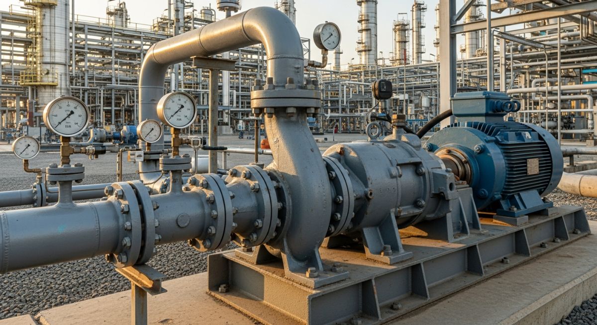
In my 20 years of piping and rotating equipment engineering, I have seen many pumps fail on the test bed and in the field. The difference between a standard industrial pump and one designed for hazardous refinery service is night and day. When you are handling flammable hydrocarbons at 400°C (750°F) or high-pressure sour water, you cannot afford to compromise. That is where the American Petroleum Institute (API) Standard 610 comes into play.
I remember a project in a major Middle Eastern refinery where a non-API pump was mistakenly specified for a light hydrocarbon transfer line. Within three weeks of commissioning, the shaft deflected under transient suction pressure, destroying the mechanical seal and causing a localized fire. We replaced it with an API 610 compliant overhung (OH2) pump. That pump has now run for eight years without a single unscheduled shutdown. This article shares the technical realities, design margins, and field-tested calculations that make these machines the backbone of our industry.
- Understand why API 610 pumps require a minimum 20-year design life and 3 years of uninterrupted continuous operation.
- Learn the structural differences between Overhung (OH), Between Bearings (BB), and Vertically Suspended (VS) pump configurations.
- Master the critical calculations for Suction Specific Speed (N_{ss}) and Net Positive Suction Head (NPSH) margins to prevent cavitation.
- Discover how to select the correct material class (from I-1 to D-2) based on fluid corrosivity and operating temperature.
Complete Course on
Piping Engineering
Check Now
Key Features
- 125+ Hours Content
- 500+ Recorded Lectures
- 20+ Years Exp.
- Lifetime Access
Coverage
- Codes & Standards
- Layouts & Design
- Material Eng.
- Stress Analysis
Why API 610 Centrifugal Pumps Matter
API 610 Design Standards: This standard establishes the minimum requirements for centrifugal pumps used in petroleum, petrochemical, and natural gas industries to ensure operational safety and mechanical integrity.
Standard industrial pumps, such as those built to ASME B73.1 or ISO 2858, are excellent for water and light chemical services. However, they lack the robust construction required to handle the extreme thermal and mechanical stresses of refinery operations. API 610 centrifugal pumps are engineered with heavy wall thicknesses, larger shaft diameters, and advanced casing designs to withstand high nozzle loads and thermal expansion without losing alignment.
Exceeding the allowable nozzle loads specified in API 610 Table 5 can cause casing distortion, shaft misalignment, and rapid bearing failure. Always perform a comprehensive piping flexibility analysis using software like CAESAR II to ensure the piping loads exerted on the pump nozzles are well within the standard’s limits.
Classifying API 610 Centrifugal Pumps Correctly
Pump Classification Framework: The API 610 standard categorizes pumps into overhung (OH), between-bearings (BB), and vertically suspended (VS) configurations to match specific pressure, temperature, and fluid properties.
Understanding these classifications is fundamental when designing a piping system or selecting equipment. Let us break down the three primary categories:
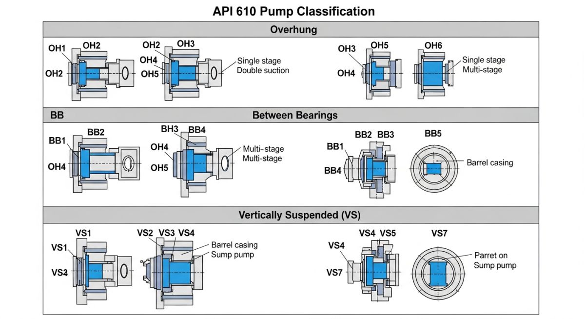
1. Overhung Pumps (OH1, OH2, OH3, OH4, OH5, OH6)
In overhung designs, the impeller is mounted on the end of a shaft that projects beyond its bearings. The most common type in refineries is the OH2 pump. This is a centerline-mounted, single-stage pump. Centerline mounting is critical because it allows the casing to expand radially and symmetrically under high temperatures, maintaining shaft alignment with the driver.
2. Between Bearings Pumps (BB1, BB2, BB3, BB4, BB5)
In between bearings designs, the impeller (or impellers) is mounted on a shaft supported by bearings at both ends. These are selected for high-flow or high-head applications. For example, the BB2 pump is a single or two-stage, radially split pump often used in hot, high-pressure services like fractionator bottoms. The BB5 pump is a double-casing, multistage barrel pump designed for extreme pressures, such as boiler feed water or high-pressure safety injection.
3. Vertically Suspended Pumps (VS1 to VS7)
These pumps are used when the available NPSH is extremely low, or when pumping from deep sumps and wet pits. The VS4 pump is a vertically suspended, single-casing sump pump with a separate discharge line, while the VS6 pump is a canned vertical pump where the liquid is contained within a suction barrel, allowing the pump to be installed below grade to maximize the available static head.
Critical Hydraulic Calculations
To prevent cavitation and ensure stable operation, we must calculate the Suction Specific Speed (N_{ss}) and verify the NPSH margin. The formula for Suction Specific Speed is:
Where:
• N = Pump rotational speed (RPM)
• Q = Flow rate at the best efficiency point (GPM) [For double-suction impellers, use Q/2]
• NPSHr = Net Positive Suction Head required at the 3% head drop (feet)
API 610 recommends that the Suction Specific Speed (N_{ss}) be limited to 11,000 (US units) to avoid internal recirculation and high vibration levels at off-design flows. If a vendor proposes a pump with an N_{ss} greater than 11,000, I advise conducting a rigorous review of their operating history and vibration data.
Selecting the correct pump type and material class is a balancing act between process conditions, safety requirements, and capital cost. The tables below provide a structured reference for making these engineering decisions.
| API Type | Configuration | Temp Limit (°C) | Max Pressure (barg) | Typical Refinery Service |
|---|---|---|---|---|
| OH2 | Overhung, Centerline Mounted | Up to 400 | 40 | Hydrocarbon transfer, column reflux, hot oil |
| BB2 | Between Bearings, 1 or 2 Stage | Up to 450 | 50 | Crude charge, vacuum bottoms, heavy gas oil |
| BB3 | Between Bearings, Axially Split | Up to 200 | 150 | Water injection, pipeline transport, lean amine |
| BB5 | Between Bearings, Double Casing | Up to 450 | 400 | Hydrocracker feed, boiler feed water, high-pressure injection |
| VS6 | Vertically Suspended, Double Casing | Up to 250 | 100 | LPG transfer, condensate extraction, low NPSHa services |
| Material Class | Casing Material | Impeller Material | Temperature Range | Applicable Standards |
|---|---|---|---|---|
| S-1 | Carbon Steel | Cast Iron | -29°C to 370°C | ASTM A216 WCB |
| S-6 | Carbon Steel | 12% Chrome SST | -29°C to 400°C | ASTM A216 / A217 |
| C-6 | 12% Chrome SST | 12% Chrome SST | -29°C to 450°C | ASTM A217 CA15 |
| A-8 | 316 Austenitic SST | 316 Austenitic SST | -196°C to 400°C | ASTM A351 CF8M |
| D-1 | Duplex Stainless Steel | Duplex Stainless Steel | -40°C to 200°C | ASTM A890 Gr 4A |
Key Design Parameters and Calculations
Pump Design Parameters: Engineers must calculate suction specific speed, nozzle loads, and NPSH margins to prevent cavitation and mechanical seal failures in high-temperature hydrocarbon services.
Before any API 610 pump is cleared for commissioning, a series of field checks must be performed. In my experience, skipping these steps often leads to premature bearing wear or mechanical seal leaks during the first 100 hours of operation.
-
Baseplate Grouting: Verify that the baseplate is fully grouted with non-shrink epoxy grout, ensuring no voids exist beneath the pump or driver mounting pads. -
Shaft Alignment: Perform cold alignment using laser alignment tools. Target offset must be within 0.05 mm (0.002 in) to account for thermal growth. -
Piping Strain Check: Unbolt the suction and discharge flanges and monitor the shaft alignment dial indicators. Shaft movement must not exceed 0.05 mm (0.002 in) during unbolting. -
Mechanical Seal Flush: Confirm that the API 682 seal flush plan (e.g., Plan 11, Plan 32, or Plan 53B) is fully operational, vented, and pressurized to the correct design parameters. -
Direction of Rotation: Perform a solo run of the driver (motor or turbine) to verify correct rotation before coupling the pump shaft.
Field Case Study: Real-World Application
At a refinery in Texas, a hot Vacuum Gas Oil (VGO) pump—an API 610 BB2 type operating at 360°C (680°F)—suffered from chronic high vibration levels (up to 12.5 mm/s RMS) and experienced mechanical seal failures every three to four months. The plant was losing significant revenue due to unscheduled unit shutdowns. A detailed field investigation revealed that the suction piping layout was highly asymmetrical, causing uneven flow distribution into the double-suction impeller. This resulted in hydraulic instability and severe cavitation, even though the calculated NPSH margin appeared adequate on paper.
We executed a two-phase remediation plan. First, we redesigned the suction piping to include a straight run of five pipe diameters directly preceding the pump suction nozzle, incorporating a flow straightener. Second, we replaced the standard impeller with a custom-engineered impeller designed with a lower NPSHr, increasing our NPSH margin from 1.1 to 1.6. Upon restarting the unit, vibration levels dropped to a stable 1.6 mm/s RMS. The pump has now operated continuously for over four years without a single seal or bearing failure, saving the refinery an estimated 1.2 million in maintenance and lost production costs.
This case highlights why we must look beyond the pump datasheet. Piping geometry, hydraulic margins, and mechanical design must be evaluated as an integrated system to achieve the high reliability that API 610 is designed to deliver.
Frequently Asked Engineering Questions
What is the primary difference between API 610 and ASME B73.1 pumps?
Why is centerline mounting preferred over foot mounting for hot services?
What is the significance of the 11,000 limit for Suction Specific Speed (N_{ss})?
How does API 610 define the required NPSH margin?
What are the most common API 682 mechanical seal plans used with API 610 pumps?
When should a double-casing barrel pump (BB5) be selected over a single-casing pump?
===

📚 Recommended Resources: API 610 centrifugal pumps
Read these Guides


Related posts:
![A mechanical sucker rod pumpjack operating in an oil field at sunset]()
What is Sucker Rod Pump System in Oil Production?
![Piping material engineer reviewing technical specifications on a tablet in an industrial plant.]()
How a Piping Material Engineer Drives Industrial Project Success
![Industrial refinery plant showing various types of static equipment]()
What is Static Equipment? Types and List of Static Equipments
![Side-by-side comparison of industrial process piping and power plant steam piping systems.]()
Differences Between ASME B31.3 and B31.1: B31.3 vs B31.1
![Large industrial steel storage tank under construction with cranes and scaffolding]()
Storage Tank Construction Method Statement: Step-by-Step Engineering Guide
![Cutaway diagram of a globe control valve highlighting the internal valve trim components]()
What is a Valve Trim? Types, Components, and Selection


