Mastering Piping Flexibility: Essential Design for Thermal Stress
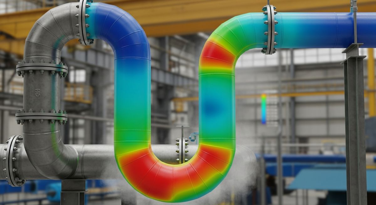
In my two decades of experience, I have seen too many catastrophic failures caused by the simple oversight of thermal expansion. When a pipe carries hot process fluids, the metal expands. If that expansion is constrained by rigid supports or equipment nozzles, the resulting stress can buckle the pipe, blow out gaskets, or tear the casing off a pump. Piping flexibility is not just a design preference; it is a fundamental requirement for structural integrity.
We design for flexibility to ensure that the forces and moments acting on sensitive equipment remain within the manufacturer’s allowable limits. By incorporating loops, offsets, or changes in direction, we allow the system to “breathe.” This guide breaks down the core principles of flexibility, the math behind the stress, and how to ensure your next project meets the rigorous standards of the industry.
Key Takeaways for Piping Engineers
- Thermal expansion is inevitable; rigid systems are failure-prone systems.
- ASME B31.3 provides the mathematical framework for calculating stress range.
- Flexibility is achieved through geometry, not just material selection.
- Equipment nozzle protection is the primary driver for flexibility analysis.
The Mechanics of Piping Flexibility Analysis
Piping Flexibility Analysis: The rigorous calculation of thermal displacement and resulting reaction forces to ensure compliance with ASME B31.3 code requirements for safe operation.
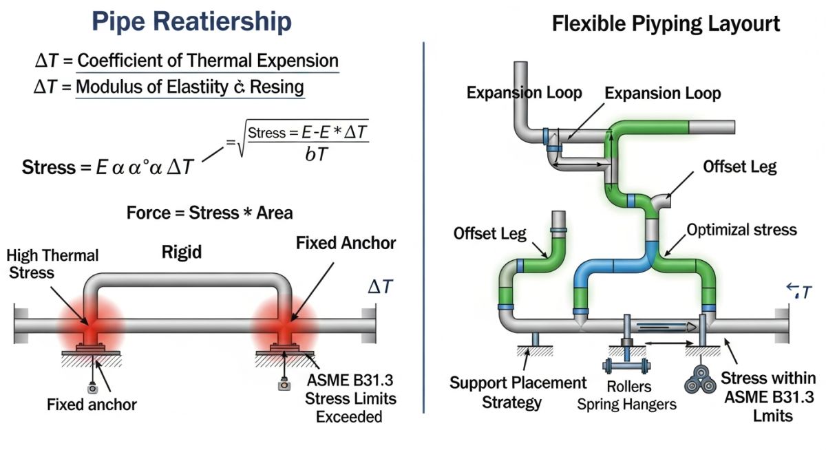
When we talk about flexibility, we are essentially managing the energy stored in a pipe due to temperature changes. The fundamental equation for thermal expansion is delta L equals alpha times L times delta T. While this seems simple, the complexity arises when the pipe is constrained. In a typical plant, we use the flexibility analysis to determine the “stress range” which is the difference between the hot and cold states of the system.
Calculating Thermal Stress and Allowables
The allowable stress range, denoted as S-A, is calculated using the formula S-A equals f times (1.25 times S-C plus 0.25 times S-H). Here, S-C is the allowable stress at the minimum metal temperature, and S-H is the allowable stress at the maximum metal temperature. The factor ‘f’ is the stress range reduction factor, which accounts for the number of full temperature cycles the system will experience over its design life.
Field Warning: The Danger of Over-Constraint
I have encountered numerous instances where field-installed supports were added to “steady” a vibrating line, inadvertently creating a rigid anchor that prevented thermal expansion. This creates a massive bending moment at the nearest equipment nozzle. Always verify that any new support does not violate the original flexibility analysis model.
To achieve the required flexibility, we manipulate the geometry of the piping layout. If the straight run between two anchors is too long, the thermal growth will exceed the allowable stress. We introduce expansion loops or “Z-bends” to increase the length of the pipe, thereby reducing the force exerted on the anchors. The flexibility factor ‘k’ and the stress intensification factor ‘i’ are critical here, as they account for the geometry of fittings like elbows and tees.
In my practice, I always perform a “cold spring” calculation if the thermal expansion is extreme. By intentionally cutting the pipe short and pulling it into place during installation, we can reduce the initial stress state. However, this requires precise field control and is only recommended when standard geometric solutions are insufficient to protect the equipment nozzles.
Flexibility Design Trade-offs: The balance between structural safety, material costs, and spatial constraints in complex industrial piping layouts.
Advantages of Flexible Design
- Prevents premature failure of rotating equipment nozzles.
- Reduces the risk of flange leakage caused by thermal cycling.
- Extends the fatigue life of the piping system significantly.
- Allows for the use of thinner wall pipe in certain high-temperature applications.
- Minimizes the structural load on pipe racks and support steel.
Disadvantages of Flexible Design
- Increases the total footprint of the piping system.
- Requires more complex support arrangements and guide systems.
- Higher initial material costs due to additional fittings and pipe length.
- Increased pressure drop due to additional elbows and bends.
- Complexity in maintenance access around expansion loops.
Industrial Flexibility Implementation: The application of thermal stress management across diverse high-temperature and high-pressure process environments.
High-Pressure Steam Distribution
In power generation plants, steam lines operate at extreme temperatures where thermal growth is significant. We utilize large-scale expansion loops and bellows expansion joints to ensure that the steam headers do not exert excessive forces on the turbine inlets, which are highly sensitive to external loading.
Cryogenic Process Piping
While often associated with heat, flexibility is equally critical in cryogenic systems where materials contract significantly. We design for “cold contraction” to prevent the pipe from pulling away from supports or causing brittle fracture at welded joints due to extreme thermal gradients.
Refinery Furnace Feed Lines
Furnace feed lines are subject to rapid temperature fluctuations during startup and shutdown cycles. By incorporating flexible piping configurations, we prevent the fatigue-induced cracking that typically occurs at the transition zones between the cold ambient piping and the high-temperature furnace inlet nozzles.
Chemical Reactor Manifolding
Reactors often have multiple nozzles in close proximity, making them highly susceptible to nozzle misalignment from thermal expansion. We use complex piping loops to isolate the reactor from the thermal growth of the main process headers, ensuring that the reactor vessel remains stress-free during operation.
In my two decades of field experience, I have observed that the primary challenge in piping design is not just the initial layout, but the management of thermal expansion cycles. When a piping system is constrained, thermal growth induces significant stress on equipment nozzles, support structures, and the pipe wall itself. The following table summarizes the critical design parameters that dictate how we evaluate flexibility under ASME B31.3 requirements.
These parameters are essential for determining the displacement stress range and ensuring that the system remains within the elastic limit during operation. Engineers must carefully evaluate the material properties, specifically the modulus of elasticity at the operating temperature, to ensure that the calculated stress does not exceed the allowable limits defined by the code. Failure to account for these variables often leads to premature fatigue failure at high-stress concentration points like branch connections or welded elbows.
| Parameter | Symbol | ASME B31.3 Reference |
|---|---|---|
| Displacement Stress Range | Se | Para 302.3.5 |
| Allowable Displacement Stress | Sa | Para 302.3.5 |
| Thermal Expansion Coefficient | alpha | Appendix C |
| Modulus of Elasticity | E | Table C-1 |
By strictly adhering to these parameters, we ensure that the piping system can absorb thermal movements without exceeding the fatigue life of the material. Always verify that your software inputs for these variables match the specific material grade and temperature profile of your project.
The complexity of modern piping systems requires a systematic approach to data management. This matrix maps the core technical entities involved in flexibility analysis to their respective industry standards and physical properties. Understanding these relationships is vital for any engineer performing stress analysis using tools like CAESAR II or AutoPIPE.
Each entity listed below plays a specific role in the structural integrity of the piping network. By mapping these to the relevant ASME standards, we create a clear audit trail for design verification. This matrix serves as a quick reference guide for identifying the governing constraints during the preliminary design phase of a project.
| Entity | Function | Standard |
|---|---|---|
| Expansion Loop | Absorb thermal growth | ASME B31.3 |
| Spring Hanger | Variable load support | MSS SP-58 |
| Expansion Joint | Axial movement compensation | EJMA Standards |
| Anchor Point | Restrain thermal movement | ASME B31.3 |
Using this matrix, engineers can quickly identify which standard governs a specific component, ensuring that the design remains compliant across all disciplines. This structured approach minimizes the risk of oversight during the complex stress analysis process.
Before finalizing any piping design, a rigorous site verification process is mandatory. In my experience, many field failures occur because the as-built conditions deviate from the theoretical model used in the stress analysis software. This checklist ensures that your design accounts for real-world constraints and site-specific conditions.
- ✓ Verify that all pipe supports are installed at the exact coordinates specified in the stress model.
- ✓ Confirm that cold spring installation, if required, has been performed according to the design drawings.
- ✓ Check that expansion joints are not over-extended or misaligned during the installation phase.
- ✓ Ensure that all anchors are rigid and properly secured to the structural steel or concrete foundation.
- ✓ Validate that the insulation thickness does not interfere with the movement of the pipe at support locations.
- ✓ Inspect for any unauthorized field modifications that might restrict the natural thermal expansion of the line.
Site verification is the final line of defense against thermal stress failures. By systematically checking these items, you ensure that the physical system behaves as predicted by your ASME B31.3 calculations. Never assume that the field installation matches the drawing without physical confirmation, especially in high-temperature or high-pressure service lines where thermal growth is significant.
Problem: Thermal Fatigue at Pump Nozzle
A high-temperature process line experienced repeated flange leaks at the pump suction nozzle due to excessive thermal growth.
- Insufficient flexibility in the piping layout near the pump.
- Rigid support placement preventing necessary thermal expansion.
- Failure to account for the thermal growth of the pump casing.
- Excessive nozzle loads exceeding the manufacturer’s allowable limits.
Outcome: Successful System Re-design
The implementation of a redesigned piping configuration resolved the stress issues and eliminated the leakage problem.
- Added an expansion loop to absorb the thermal displacement.
- Replaced rigid supports with spring hangers to allow for movement.
- Reduced nozzle loads by 40 percent, well within the allowable range.
- Achieved zero leakage over three years of continuous operation.
This case study highlights the importance of early-stage flexibility analysis. My recommendation is to always perform a sensitivity analysis on your support locations to ensure that minor field adjustments do not compromise the overall flexibility of the system.
What is the primary purpose of piping flexibility?
- Prevents structural failure of pipe walls due to thermal fatigue.
- Protects sensitive equipment nozzles from excessive external forces and moments.
- Ensures the integrity of flange connections by minimizing thermal-induced bending.
- Maintains the alignment of the piping system throughout its operational temperature range.
How does ASME B31.3 define displacement stress?
- It is calculated based on the range of movement between the cold and hot conditions.
- The code provides specific formulas in paragraph 302.3.5 to determine the allowable stress range.
- This stress is considered secondary, meaning it is self-limiting and does not lead to catastrophic failure in a single cycle.
- The analysis must account for the modulus of elasticity at the operating temperature.
When is a formal stress analysis required?
- High-temperature services where thermal growth exceeds standard tolerances.
- Systems connected to rotating equipment like pumps, compressors, or turbines.
- Piping with large diameters or thin wall thicknesses that are prone to buckling.
- Any system where the calculated displacement stress might exceed the allowable limits defined by ASME B31.3.
What is the role of cold springing?
- It involves cutting the pipe slightly shorter than the required gap to force it into position.
- This creates an initial stress in the opposite direction of the thermal expansion.
- As the pipe heats up, the thermal expansion relieves the initial cold stress, resulting in lower operating loads.
- It is a common technique for high-temperature lines where nozzle loads are critical.
How do expansion loops improve flexibility?
- They convert axial thermal expansion into bending stress, which is easier for the pipe to accommodate.
- The geometry of the loop determines the amount of displacement it can handle.
- Properly designed loops reduce the stress concentration at elbows and branch connections.
- They are essential in long straight runs where thermal growth would otherwise cause buckling or support failure.
What are the risks of ignoring flexibility?
- Catastrophic failure of equipment nozzles due to excessive thermal loads.
- Fatigue cracking at welded joints, leading to hazardous process leaks.
- Permanent deformation of the piping system, causing misalignment and drainage issues.
- Damage to support structures and foundations due to unexpected thermal forces.
📚 Recommended Resources: Piping Flexibility
Read these Guides
🎓 Advanced Training



Complete Course on
Piping Engineering
Check Now
Key Features
- 125+ Hours Content
- 500+ Recorded Lectures
- 20+ Years Exp.
- Lifetime Access
Coverage
- Codes & Standards
- Layouts & Design
- Material Eng.
- Stress Analysis
