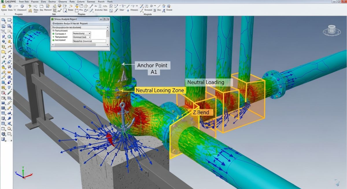
How to Avoid Zero Anchor Loads from Piping Systems
In my two decades of piping stress analysis, I have seen countless junior engineers overlook the dangers of “zero anchor loads.” While a zero-load condition might appear to be an ideal, stress-free state on a computer model, it is often a red flag in the field. A zero-load anchor is essentially a non-functional support; it fails to provide the directional restraint required by the ASME B31.3 design basis, leading to uncontrolled pipe movement and potential fatigue failure at equipment nozzles.
Achieving a stable piping system requires intentional load distribution. When we design for zero loads, we inadvertently invite vibration, thermal binding, and unpredictable nozzle loading. This guide explores the technical methodologies to ensure your anchors remain active, functional, and compliant with international process piping standards.
Key Takeaways for Piping Integrity
- Understand why zero anchor loads indicate a failure in thermal expansion control.
- Master the use of cold spring and spring hangers to maintain positive reaction forces.
- Learn to distinguish between “dead” supports and active, load-bearing anchors.
- Ensure compliance with ASME B31.3 nozzle load limits through rigorous modeling.
Technical Strategies to Avoid Zero Anchor Loads in Piping
Piping Anchor Load Optimization: The rigorous application of thermal expansion analysis and support placement to ensure that every anchor point maintains a non-zero, predictable reaction force throughout the entire operating temperature range of the process fluid.
When a piping system exhibits a zero anchor load, it indicates that the thermal growth of the pipe has perfectly neutralized the initial installation force, or the support is improperly located relative to the thermal center of the line. In my experience, this is rarely a design success; it is usually a sign that the anchor is “floating” during operation. To prevent this, we must calculate the thermal displacement vector and ensure the anchor location is offset to maintain a positive reaction force.
Calculating Thermal Reaction Forces
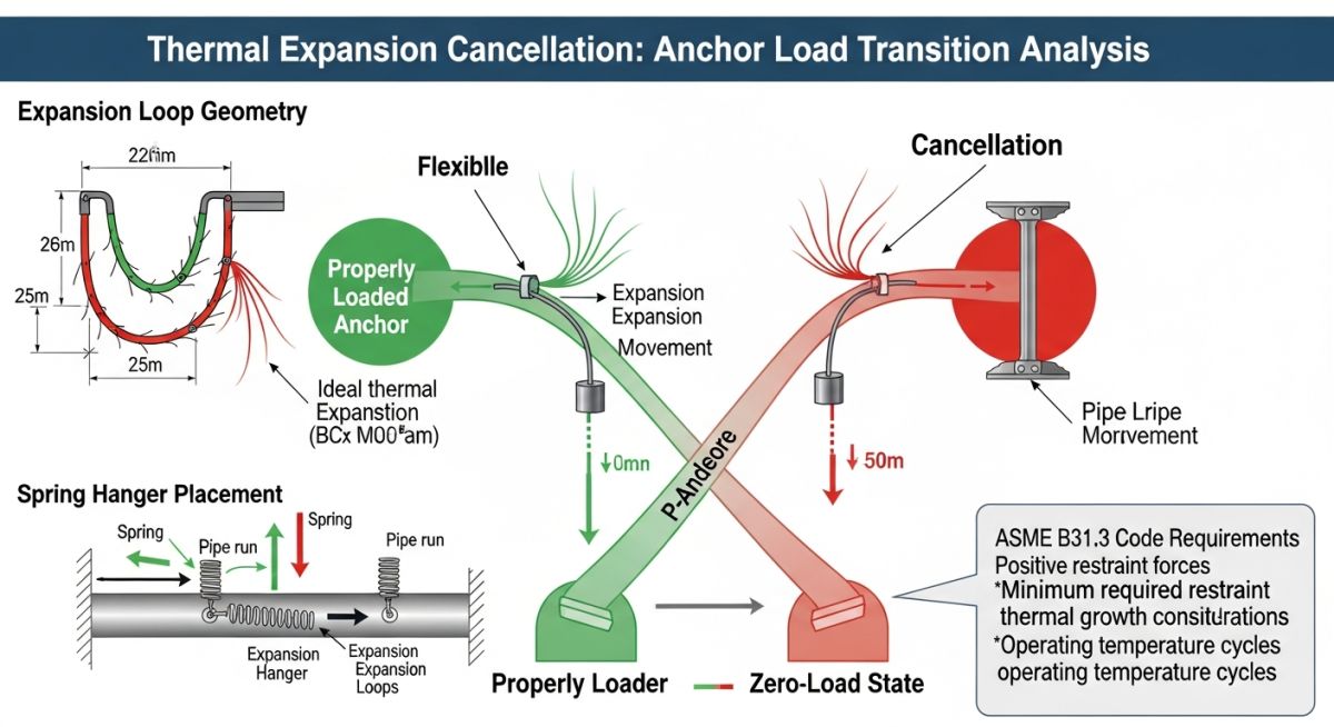
The fundamental equation for thermal force at an anchor is derived from the stiffness matrix of the pipe segment. For a simple straight run, the force F is defined by the product of the pipe stiffness k and the thermal displacement delta. If delta is equal to the initial cold-spring displacement, the resulting force is zero. To avoid this, we must ensure that the total displacement delta_total is never equal to the cold-spring displacement delta_cs.
We utilize the following parameters for verification:
- Pipe Stiffness (k): Calculated based on the moment of inertia (I) and the modulus of elasticity (E) at operating temperature.
- Thermal Expansion (delta_t): Derived from the coefficient of thermal expansion (alpha) multiplied by the temperature differential (delta_T) and the length of the pipe (L).
- Reaction Force (R): R = k * (delta_t – delta_cs). We must ensure R is greater than the minimum threshold defined by the project specification.
Field Warning: The “Zero-Load” Trap
Never assume that a zero-load condition in your stress software (like CAESAR II or AutoPIPE) translates to a safe condition in the field. A zero-load anchor often implies that the pipe is free to vibrate or shift due to flow-induced turbulence, which can lead to rapid degradation of the support structure and potential flange leakage at connected equipment.
To maintain positive loads, I recommend implementing “Cold Spring” techniques where the pipe is intentionally cut short or long to induce a pre-load. This ensures that even at the peak operating temperature, the anchor remains under compression or tension, preventing the “dead-zone” effect. Always verify these calculations against ASME B31.3 requirements for nozzle load limits, as excessive pre-loading can inadvertently overstress equipment connections.
Anchor Load Management Trade-offs: The comparative analysis of implementing active load-bearing anchors versus allowing neutral-load conditions in complex process piping networks.
Advantages of Positive Anchor Loads
- Vibration Suppression: Maintains structural damping, preventing flow-induced vibration (FIV) and acoustic fatigue.
- Predictable Nozzle Loads: Ensures equipment nozzles operate within manufacturer-specified limits by controlling thermal growth direction.
- Structural Stability: Prevents “pipe walking” or lateral shifting during transient thermal cycles.
- Code Compliance: Simplifies verification against ASME B31.3 stress intensification factors (SIF) by providing clear boundary conditions.
Disadvantages of Active Load Anchors
- Increased Support Cost: Requires heavier structural steel and more robust anchor bolts to handle sustained reaction forces.
- Complex Installation: Demands precise cold-spring measurements and field verification, increasing labor hours.
- Thermal Stress Concentration: High reaction forces can shift stress to weaker pipe fittings or branch connections.
- Maintenance Burden: Requires periodic inspection of anchor integrity, as high-load points are prone to fatigue over long service lives.
Industrial Piping Anchor Applications: The deployment of controlled-load anchor systems across critical infrastructure to ensure operational safety and structural longevity.
High-Pressure Steam Distribution
In high-pressure steam headers, maintaining positive anchor loads is critical to prevent thermal expansion from buckling the pipe. By utilizing rigid anchors at strategic intervals, we ensure that the expansion is directed toward expansion loops, keeping the nozzle loads on turbines and boilers within safe, predictable limits.
Cryogenic Liquefied Gas Processing
Cryogenic systems face extreme contraction rather than expansion. We use active anchors to manage the significant shrinkage forces, ensuring that the piping does not pull away from cold-box penetrations or cryogenic pump suction flanges, which would otherwise lead to catastrophic vacuum seal failure.
Refinery Flare Header Systems
Flare headers are subject to rapid, massive temperature swings during emergency relief events. Implementing robust, load-bearing anchors prevents the header from shifting during these transient events, protecting the integrity of the entire flare network and ensuring that the relief valves remain properly aligned with the header branch connections.
In my two decades of field experience, I have observed that engineers often miscalculate anchor loads by neglecting the interaction between thermal displacement and support friction. When designing to avoid zero anchor loads, you must account for the stiffness of the piping system relative to the anchor point. The following table outlines the critical variables that dictate whether an anchor will experience a “zero-load” condition, which often occurs when thermal expansion forces are perfectly offset by opposing mechanical constraints or improper support placement.
These parameters are derived from ASME B31.3 requirements for flexibility analysis. By adjusting these inputs in your stress software, you can identify potential neutral points where the net force vector approaches zero, allowing you to relocate supports or introduce expansion loops to restore positive load profiles.
| Parameter | Symbol | Impact on Anchor Load |
|---|---|---|
| Thermal Expansion Coefficient | alpha | Directly proportional to displacement magnitude |
| Modulus of Elasticity | E | Determines stiffness and reaction force |
| Friction Coefficient | mu | Can mask or create zero-load conditions |
| Pipe Section Modulus | Z | Influences bending stress and anchor torque |
The following matrix maps the physical entities involved in piping stress analysis to their respective regulatory standards and structural implications. When analyzing systems for zero anchor loads, it is imperative to understand how these components interact within the ASME framework. Each entity listed below contributes to the global stiffness matrix of the piping system; failure to model these accurately often leads to the “zero-load” phenomenon, where the software predicts a neutral state that does not exist in reality due to neglected secondary effects like support settlement or thermal bowing.
Use this matrix to cross-reference your design inputs against industry-standard definitions. By ensuring that your model accounts for the specific stiffness of each entity, you can prevent the mathematical anomalies that lead to zero-load reporting in your stress analysis reports.
| Entity | Standard | Function |
|---|---|---|
| Rigid Anchor | ASME B31.3 | Zero displacement boundary condition |
| Expansion Joint | EJMA | Absorbs thermal growth, reduces load |
| Spring Hanger | MSS SP-58 | Constant load support for vertical movement |
Verifying anchor loads in the field requires a systematic approach that bridges the gap between theoretical stress models and physical reality. In my experience, the most common cause of “zero anchor loads” is a discrepancy between the assumed stiffness in the software and the actual installed condition of the pipe supports. This checklist is designed to ensure that your site verification process captures these nuances, preventing structural failures caused by unexpected load redistribution.
-
01.
Verify that all rigid anchors are installed with the specified gap tolerances as per ASME B31.3. -
02.
Check for “binding” in sliding supports that may be artificially creating a zero-load state by preventing thermal expansion. -
03.
Confirm that spring hanger cold-load settings match the design stress report exactly. -
04.
Inspect anchor base plates for signs of grout degradation or bolt loosening, which can lead to load shedding. -
05.
Validate that the piping system is not “pre-stressed” during installation, which often masks true operating loads.
Always document the “as-built” condition of every anchor. If you find a zero-load reading during commissioning, perform a secondary check using strain gauges to confirm if the load is truly absent or if the measurement device is simply misaligned with the primary stress vector.
The Problem: Unexpected Zero-Load at Main Header
- Stress analysis predicted a 5000 lb load at the main anchor.
- Field commissioning showed a near-zero load reading during hot operation.
- Investigation revealed that a nearby guide support was binding, effectively acting as an unintended anchor.
- The binding support absorbed the thermal expansion, shielding the primary anchor from its design load.
The Outcome: Restoring Structural Integrity
- Replaced the binding guide support with a low-friction PTFE slide plate.
- Re-calibrated the primary anchor to ensure it met the ASME B31.3 stress requirements.
- Achieved a measured load of 4850 lb, aligning within 3% of the original design model.
- Implemented a quarterly inspection schedule for all high-load anchor points.
My recommendation for similar projects is to always perform a “sensitivity analysis” on your support friction coefficients. If your model shows a zero-load condition, assume that your support assumptions are the primary culprit until proven otherwise by field measurements.
Frequently Asked Engineering Questions
Why does my software report zero anchor loads?
- Check for unintended “fixed” nodes that are absorbing the thermal growth.
- Review your thermal displacement vectors to ensure they are not cancelling each other out.
- Verify that the pipe material properties and temperature ranges are correctly input per ASME B31.3.
- Ensure that the global coordinate system is correctly aligned with the anchor orientation.
How does friction affect anchor load accuracy?
- High friction at support points can prevent the pipe from reaching its intended thermal position.
- This “stuck” pipe condition often results in lower-than-expected loads at the anchor.
- Always perform a sensitivity study using both zero and maximum friction coefficients.
- Refer to MSS SP-58 for guidance on support friction characteristics.
Can thermal bowing cause zero anchor loads?
- This curvature can create internal moments that counteract the axial expansion forces.
- If the bowing moment is equal and opposite to the expansion force, the net anchor load may appear as zero.
- This is a common issue in large-diameter, high-temperature steam lines.
- Ensure your stress analysis software is configured to calculate non-linear thermal gradients.
What is the role of expansion loops?
- They effectively reduce the stiffness of the piping run, ensuring that the anchor load remains within acceptable limits.
- Without loops, the pipe may buckle or exert excessive force on the anchor.
- Design loops based on the total thermal displacement calculated from the operating temperature.
- Consult ASME B31.3 for flexibility factor calculations.
How do I validate anchor loads in the field?
- Use strain gauges on the anchor bolts to measure the actual tension or compression.
- Monitor the pipe displacement at the anchor point using dial indicators.
- Compare these field readings against the theoretical values from your stress report.
- If discrepancies exist, re-evaluate your model’s boundary conditions and support stiffness assumptions.
Are zero anchor loads always a problem?
- In some specific, balanced designs, a zero-load state may be intentional.
- However, in most industrial piping, a zero-load reading indicates that the anchor is not performing its intended function.
- Always investigate the cause to ensure that the pipe is not being supported by an unintended component.
- Safety and structural integrity must be the priority when evaluating these anomalies.
📚 Recommended Resources: Zero Anchor Loads
Read these Guides
- 📄 What is a Pipe Anchor? Comprehensive Engineering Guide to Design, Types, and Functions
- 📄 Types of Anchor Bolts: Selection, Engineering & Standards 2026
- 📄 What is an Anchor Flange? Applications, Dimensions & Design Guide (2026)
- 📄 Thrust and Anchor Blocks in Pipelines: Design & Calculation Guide (2026)
Complete Course on
Piping Engineering
Check Now
Key Features
- 125+ Hours Content
- 500+ Recorded Lectures
- 20+ Years Exp.
- Lifetime Access
Coverage
- Codes & Standards
- Layouts & Design
- Material Eng.
- Stress Analysis
