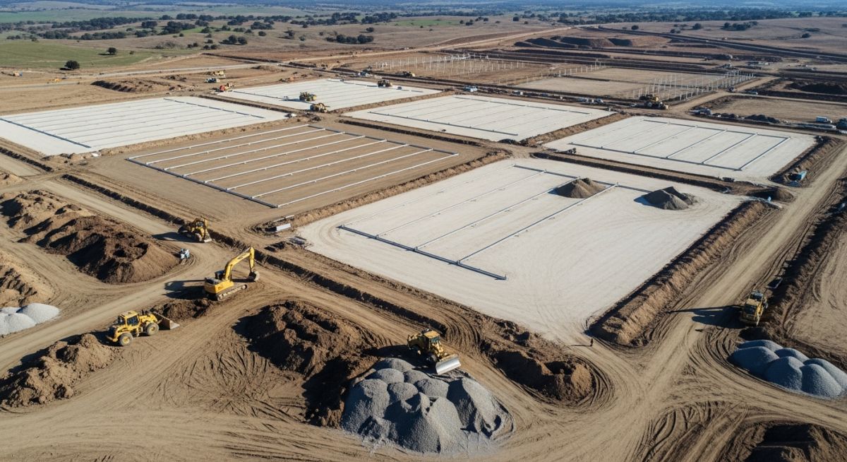
Earthwork Optimization for Solar Farms: A Civil Engineering Guide
In my two decades of managing large-scale infrastructure projects, I have observed that the most significant budget overruns in renewable energy construction rarely stem from the solar modules themselves. Instead, they originate from poor site preparation and inefficient earthwork strategies. When we talk about Earthwork Optimization for Solar Farms, we are essentially balancing the delicate interplay between topography, tracker mechanical limits, and geotechnical constraints.
A poorly graded site leads to excessive soil export or import, which can inflate project costs by millions. By leveraging advanced modeling and precise grading techniques, we can transform a challenging, undulating landscape into a high-performance solar asset. This guide explores the technical methodologies required to achieve this balance effectively.
Key Takeaways
- Minimize mass haul distances to reduce fuel and equipment rental costs.
- Align tracker rows with existing contours to reduce the need for aggressive benching.
- Utilize Civil 3D surface analysis to identify optimal grading zones early in the design phase.
- Integrate stormwater management directly into the grading plan to avoid secondary drainage infrastructure costs.
Technical Strategies for Earthwork Optimization for Solar Farms
Earthwork Optimization for Solar Farms: The application of computational surface modeling and geotechnical analysis to align site topography with the mechanical slope tolerances of solar tracking systems, thereby minimizing soil movement and environmental impact.
To achieve true optimization, we must first define the mechanical constraints of the solar trackers. Most single-axis trackers have a maximum slope tolerance, typically ranging from 10% to 15% along the north-south axis. Exceeding these limits requires either structural reinforcement of the torque tube or, more commonly, extensive site grading.
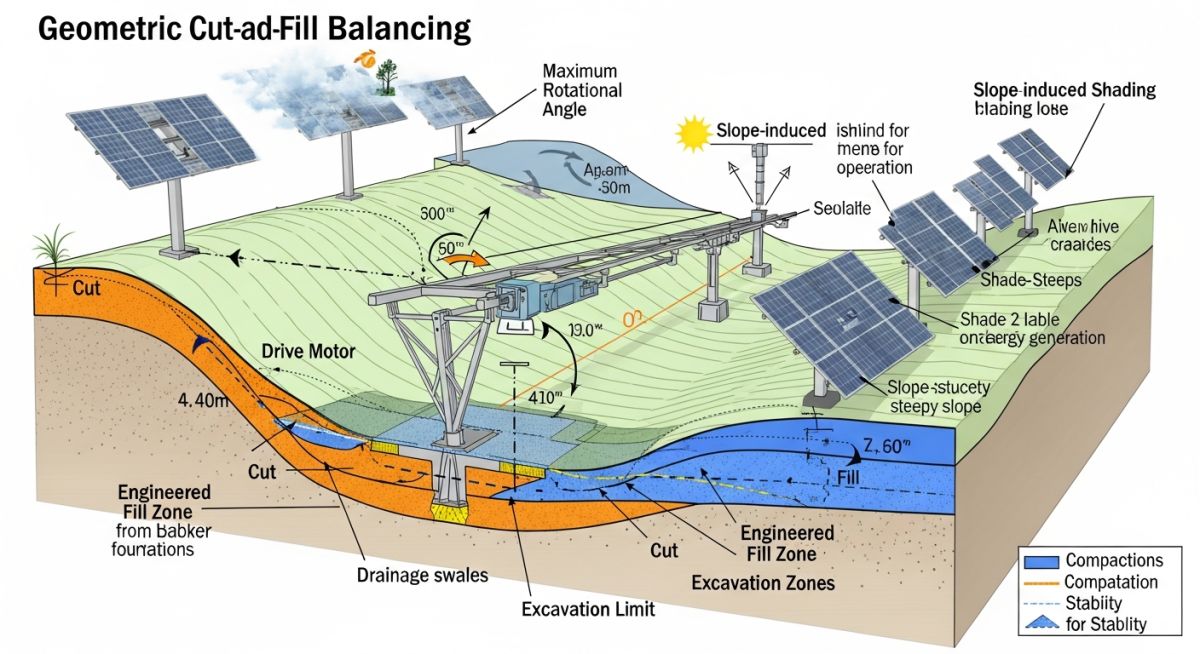
The Cut and Fill Balancing Equation
The objective is to achieve a net-zero earthwork balance, where the volume of cut equals the volume of fill, adjusted for the soil shrinkage factor. The basic calculation is defined as:
In my experience, failing to account for the shrinkage factor—which typically ranges from 10% to 20% depending on soil composition—is the most common error in preliminary estimates. We utilize Autodesk Civil 3D to generate a “Best Fit” surface that minimizes the vertical deviation from the existing ground while satisfying the tracker slope requirements.
Field Warning: Geotechnical Sensitivity
Never assume uniform soil behavior across a large site. Variations in moisture content and soil density can lead to differential settlement, which is catastrophic for tracker alignment. Always conduct a comprehensive geotechnical survey before finalizing your grading plan to ensure the subgrade can support the required foundation loads.
Civil 3D Optimization Workflow
The workflow begins with creating a high-resolution Digital Terrain Model (DTM). We then apply “Feature Lines” along the proposed tracker rows. By adjusting the elevations of these feature lines, we can simulate the grading impact in real-time. The goal is to keep the grading within the “pad” area of the tracker, avoiding the need to grade the entire site.
This approach, often called “surgical grading,” significantly reduces the environmental footprint and the cost of erosion control measures. By adhering to ASCE standards for site development, we ensure that the final surface maintains adequate drainage, preventing ponding that could lead to soil saturation and foundation failure.
Grading Optimization Trade-offs: The strategic evaluation of site modification techniques against long-term operational costs and environmental compliance requirements.
Advantages
- Significant reduction in heavy equipment mobilization and fuel consumption.
- Lower erosion control costs due to minimal soil disturbance.
- Improved tracker performance through consistent row alignment.
- Faster construction timelines by reducing total volume of earth moved.
- Enhanced site drainage, reducing long-term maintenance of access roads.
Disadvantages
- Requires high-precision survey data and advanced modeling software.
- Increased upfront engineering design time and specialized labor costs.
- Potential for “hidden” costs if geotechnical reports are inaccurate.
- Complexity in managing regulatory permits for site modification.
- Risk of over-optimization leading to insufficient drainage in extreme weather.
Solar Site Development Applications: The practical implementation of earthwork optimization across diverse terrain types and utility-scale project requirements.
Utility-Scale Desert Installations
In arid environments, minimizing soil disturbance is critical to prevent dust generation and maintain the existing desert crust. We use surgical grading to install trackers on natural slopes, avoiding the need for massive land clearing that would otherwise trigger significant environmental mitigation costs.
Brownfield Solar Redevelopment
Redeveloping former industrial sites often involves contaminated soil that cannot be moved off-site. Optimization here focuses on “capping” and minimal surface grading to avoid disturbing legacy contaminants, requiring precise tracker placement to match existing site elevations.
Agricultural Land Conversion
When converting farmland, the goal is to preserve topsoil and maintain existing agricultural drainage tiles. Optimization strategies allow us to work around these features, ensuring that the land remains viable for future use while maximizing the solar energy yield per acre.
Effective site grading requires a precise understanding of how soil properties and tracker geometry interact with the natural topography. In my experience, the following table outlines the critical design thresholds that dictate whether a site requires extensive mechanical intervention or can be managed through minor localized adjustments.
These parameters are derived from standard ASCE guidelines and common industry practices for utility-scale solar installations. By aligning your design with these values, you can significantly reduce the volume of earth moved, thereby lowering the overall project carbon footprint and capital expenditure.
| Parameter | Recommended Limit | Impact on Cost |
|---|---|---|
| Max North-South Slope | 10% to 15% | High (Tracker structural limits) |
| Max East-West Slope | 5% | Moderate (Installation speed) |
| Compaction Density | 95% Standard Proctor | Low (Structural integrity) |
| Grading Tolerance | +/- 0.1 feet | High (Surveying intensity) |
Always verify these limits against the specific tracker manufacturer’s installation manual, as proprietary mechanical linkages often impose stricter constraints than general civil engineering standards.
The following matrix maps the core technical entities involved in Earthwork Optimization for Solar Farms to their respective regulatory and operational frameworks. Understanding these relationships is vital for project managers who must balance geotechnical requirements with electrical layout constraints.
This mapping ensures that every cubic yard of soil moved is accounted for in the project’s Civil 3D model, preventing costly rework during the construction phase. By standardizing these inputs, engineering teams can maintain consistency across multiple project sites.
| Entity | Standard/Ref | Primary Function |
|---|---|---|
| Cut/Fill Volume | ASTM D698 | Mass balance calculation |
| Erosion Control | SWPPP | Stormwater management |
| Tracker Alignment | OEM Specs | Mechanical tracking range |
Utilizing this matrix during the preliminary design phase allows for rapid identification of potential conflicts between site topography and the required tracker tilt angles.
Earthwork Optimization for Solar Farms requires a rigorous verification process to ensure that the digital model matches the physical reality of the site. Before breaking ground, I always mandate a comprehensive site walk-through to validate the assumptions made during the design phase.
-
Topographic Accuracy: Verify that the drone-based survey data aligns with the Civil 3D surface model within a 0.05-foot tolerance. -
Soil Composition: Confirm that the geotechnical report accurately reflects the cut-and-fill suitability, specifically regarding moisture content and expansion potential. -
Drainage Pathways: Ensure that all proposed swales and retention basins are clearly staked and do not conflict with planned underground electrical conduit runs. -
Tracker Clearance: Validate that the lowest point of the tracker assembly maintains the required ground clearance at the maximum tilt angle across all graded areas.
Failure to perform these checks often leads to “change orders” during the construction phase, which can inflate project costs by 15-20%. Always document these findings in a centralized project management system to ensure accountability and traceability for all stakeholders involved in the site development.
The Challenge: Excessive Grading Costs
A 50MW solar project in a rolling terrain environment faced a 40% budget overrun due to inefficient site grading strategies that ignored natural drainage patterns.
- Over-reliance on “flat-grading” instead of “contour-following” designs.
- Inaccurate soil swell factors leading to massive off-site disposal costs.
- Lack of coordination between civil grading and tracker structural mounting heights.
The Outcome: Optimized Earthwork Success
By re-engineering the site using a balanced cut-and-fill approach and adjusting tracker row orientation, we achieved significant project savings.
- Reduced total earth movement volume by 28% through site-specific grading.
- Eliminated the need for off-site soil disposal, saving 250,000 in logistics.
- Improved drainage efficiency, reducing long-term erosion maintenance costs by 15%.
My recommendation for future projects is to prioritize early-stage Civil 3D optimization. By simulating multiple grading scenarios before finalizing the site plan, you can identify the “sweet spot” where tracker performance and earthwork costs are perfectly balanced.
How does tracker sensitivity affect grading?
- Exceeding the manufacturer’s slope limit forces the use of expensive custom-length piles.
- Grading must be performed to ensure the tracker row remains within the allowable tilt range.
- Failure to account for this leads to increased motor torque requirements and premature mechanical wear.
What is the role of Civil 3D in optimization?
- Automated volume calculations allow for rapid iteration of grading plans.
- Integration with GIS data ensures that environmental constraints are respected.
- The software helps visualize the impact of grading on drainage patterns before construction begins.
How do you balance cut and fill?
- Calculate the shrinkage and swell factors of the local soil types.
- Adjust the site finished grade to achieve a net-zero volume balance.
- Use mass-haul diagrams to optimize the movement of soil across the site.
Why is drainage integration critical?
- Properly designed swales prevent water from pooling around sensitive electrical equipment.
- Compliance with local stormwater permits is mandatory for project approval.
- Effective drainage reduces the risk of foundation settlement over the project lifespan.
What are the cost minimization strategies?
- Adopt contour-following designs to reduce the need for massive site leveling.
- Optimize the layout to align with natural site topography.
- Use high-precision GPS-guided grading equipment to reduce survey time and rework.
How do you handle soil compaction?
- Perform field density tests to verify compliance with design specifications.
- Use appropriate compaction equipment based on the soil type and moisture content.
- Ensure that backfill around piles is compacted in thin lifts to maintain structural integrity.
Complete Course on
Piping Engineering
Check Now
Key Features
- 125+ Hours Content
- 500+ Recorded Lectures
- 20+ Years Exp.
- Lifetime Access
Coverage
- Codes & Standards
- Layouts & Design
- Material Eng.
- Stress Analysis
