Piping Engineer vs Pipeline Engineer: Key Differences and Roles Explained
In my 20 years of experience executing major oil and gas projects, I have often noticed a common point of confusion among clients and junior engineers: the distinction between piping engineering and pipeline engineering. While both fields deal with the transport of fluids through cylindrical conduits, they operate in entirely different engineering dimensions. Confusing these roles on a project can lead to severe design mismatches, regulatory non-compliance, and cost overruns.
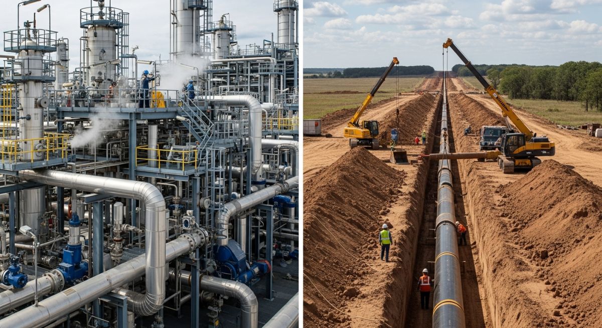
Piping engineering is a highly concentrated, three-dimensional puzzle. It deals with complex networks of pipes confined within a plant’s battery limits—such as refineries, chemical plants, or offshore platforms. On the other hand, pipeline engineering is a linear, geographical challenge. It involves transporting fluids over hundreds of kilometers across varying terrains, public roads, rivers, and international borders.
Key Takeaways from an Industry Expert
- Code Jurisdictions: Piping design is governed by ASME B31.3, while pipelines fall under ASME B31.4 or ASME B31.8.
- Stress Profiles: Piping stress is dominated by thermal expansion and high-temperature gradients, whereas pipeline stress is dominated by soil-pipe interaction, geohazards, and internal pressure.
- Material Selection: Piping utilizes a wide array of alloy steels, stainless steels, and non-metallics; pipelines primarily rely on high-strength carbon steel line pipes (API 5L grades).
- Boundary Limits: The physical transition between these two disciplines occurs at the plant battery limit, typically at the first isolation valve or pig launcher/receiver flange.
Piping Engineer vs Pipeline Engineer: Core Technical Differences
To understand the technical divide, we must look at how each discipline calculates wall thickness and manages stress. The mathematical models and safety factors used by a piping engineer are fundamentally different from those used by a pipeline engineer.
1. Wall Thickness Calculations and Design Philosophy
In facility piping design under ASME B31.3, the minimum required wall thickness (t) for straight pipe under internal pressure is calculated using the following formula:
Where:
• P = Internal design gage pressure
• D = Outside diameter of the pipe
• S = Stress value for material from Table A-1
• E = Quality factor from Table A-1A or A-1B
• W = Weld joint strength reduction factor
• Y = Coefficient from Table 304.1.1
Conversely, a pipeline engineer working under ASME B31.8 (for gas transmission) uses a design formula based on the Barlow equation, modified by environmental and location factors:
Where:
• S = Specified Minimum Yield Strength (SMYS) of the pipe
• F = Design Factor (determined by the Class Location, ranging from 0.72 for sparsely populated Class 1 areas to 0.40 for densely populated Class 4 areas)
• E = Longitudinal joint factor
• T = Temperature derating factor
2. Stress Analysis and Support Systems
Piping stress analysis is highly focused on thermal expansion. Because process plants operate at extreme temperatures (sometimes exceeding 500°C), pipes expand significantly. Piping engineers use software like CAESAR II to design expansion loops, select spring hangers, and place rigid anchors to guide this thermal growth without overloading equipment nozzles (such as pumps and compressors governed by API 610).
Pipeline stress analysis, however, is dominated by soil-pipe interaction. Pipelines are buried underground, meaning the surrounding soil acts as a continuous, non-linear spring restraining the pipe. Pipeline engineers must analyze geohazards, soil settlement, seismic activity, and road crossings. They use specialized software like AutoPIPE or pipeline-specific modules to model how the soil restrains the pipe during pressure and temperature changes.
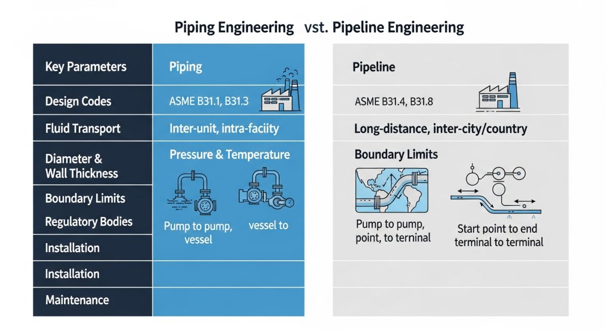
| Design Parameter | Piping Engineering (Plant) | Pipeline Engineering (Cross-Country) |
|---|---|---|
| Primary Design Codes | ASME B31.3, ASME B31.1 | ASME B31.4, ASME B31.8, ISO 13623 |
| Material Standards | ASTM A106, A333, A312, Alloy Steels | API 5L (Grades X52 to X80) |
| Dominant Stress Type | Thermal expansion, cyclic fatigue, structural loads | Soil restraint, hoop stress, geohazards, bending |
| Support Methods | Pipe racks, spring hangers, shoes, guides | Continuous soil bedding, anchor blocks, trenching |
| Corrosion Mitigation | Corrosion allowance (1.5mm to 6mm), painting | External coatings (3LPE/FBE) + Cathodic Protection |
| Inspection & Testing | Hydrotesting (1.5x design pressure), NDT (RT/UT) | Hydrotesting (1.25x), Intelligent Pigging (ILI) |
| Technical Entity | Piping Application | Pipeline Application | Reference Standard |
|---|---|---|---|
| Flanges & Fittings | ASME B16.5, ASME B16.9, ASME B16.11 | MSS SP-75, ASME B16.47 (Series A/B) | ASME Standards |
| Valves | API 600, API 602, API 609 (Gate, Globe, Butterfly) | API 6D (Full-bore Ball valves for pigging) | API Standards |
| Overpressure Protection | Pressure Safety Valves (PSV) per ASME Sec VIII | Surge relief systems, fast-acting gas valves | API 520 / API 521 |
| Stress Software | CAESAR II, AutoPIPE (Facility mode) | CAESAR II (Pipeline module), PIPENET, Stoner | Industry Software |
Piping Engineer vs Pipeline Engineer Interface Checklist
When executing a project that transitions from a cross-country pipeline into a processing facility, the interface between the piping engineer and the pipeline engineer must be managed with extreme precision. Use this checklist to verify that no design parameters are missed at the battery limit.
Interface Verification Checkpoints
-
Define Code Transition Point: Clearly mark the exact physical location where ASME B31.4/B31.8 ends and ASME B31.3 begins (typically the first isolation valve or the pig launcher/receiver flange).
-
Coordinate Design Pressures: Ensure that the pipeline design pressure matches the facility piping design pressure, taking into account potential transient surge pressures calculated via hydraulic analysis.
-
Verify Material Compatibility: Confirm that the transition weld between high-strength pipeline steel (e.g., API 5L X65) and facility piping steel (e.g., ASTM A106 Gr. B) uses a qualified welding procedure with appropriate pre-heat and post-weld heat treatment (PWHT).
-
Anchor Block Load Sharing: Verify that the pipeline anchor block is designed to absorb all soil-restrained axial forces, preventing them from transferring into the plant’s piping system and overloading equipment nozzles.
-
Cathodic Protection Isolation: Ensure that monolithic isolation joints are installed at the battery limit to electrically isolate the buried pipeline (which uses active cathodic protection) from the grounded plant piping system.
-
Pigging Clearance: Confirm that all piping components upstream of the pig receiver (including valves and bends) have a constant internal diameter matching the pipeline to prevent the pig from getting stuck.
Field Case Study: Real-World Application
The Problem: Battery Limit Stress Overload
During the commissioning phase of a gas processing plant in the Middle East, the plant’s pig receiver nozzle experienced severe distortion, leading to flange leakage. The pipeline stress engineer and the facility piping engineer had worked in silos. The pipeline engineer assumed the plant piping would absorb the thermal expansion, while the piping engineer assumed the buried pipeline was fully self-restrained by the soil. As a result, the high thermal expansion from the hot process piping pushed directly into the pipeline, causing excessive bending moments on the pig launcher nozzle that exceeded API 6D limits by 180%.
The Outcome: Integrated Stress Resolution
I was brought in to resolve this critical interface issue. We performed a coupled stress analysis using CAESAR II, modeling both the buried pipeline and the above-ground facility piping in a single software file. To solve the problem, we designed a massive concrete anchor block at the fence line, isolating the pipeline’s soil-restrained forces from the plant’s thermal movements. We also added a 3D expansion loop on the facility side. This reduced the nozzle loads by 65%, completely stopped the flange leakage, and brought the entire system into full compliance with both ASME B31.3 and ASME B31.8.
This case study highlights why the roles of a piping engineer and a pipeline engineer must be coordinated. A failure to understand how soil-pipe interaction on the pipeline side affects rigid piping supports on the facility side can lead to catastrophic mechanical failures.
Frequently Asked Engineering Questions
What is the primary difference in design codes between a piping engineer and a pipeline engineer?
How does stress analysis differ between piping and pipeline systems?
Can a piping engineer easily transition to a pipeline engineering role?
Why do pipeline designs use variable design factors while piping designs use fixed safety factors?
How is corrosion protection managed differently in piping versus pipelines?
What are the typical software tools used by piping and pipeline engineers?
Complete Course on
Piping Engineering
Check Now
Key Features
- 125+ Hours Content
- 500+ Recorded Lectures
- 20+ Years Exp.
- Lifetime Access
Coverage
- Codes & Standards
- Layouts & Design
- Material Eng.
- Stress Analysis