Table of Contents
What is a Modular Process Skid? Design and Engineering Guide
In my 20+ years of piping engineering, I have watched the industry undergo a massive paradigm shift. Gone are the days when we spent months in the field, battling unpredictable weather, labor shortages, and safety hazards to build process plants stick-by-stick. Today, fast-track projects demand speed, precision, and cost-predictability. This is where the modular process skid comes into play.
When I design a modular system, I look at it as a highly engineered machine. Every square inch of the structural frame is optimized to support heavy static loads while surviving the dynamic forces of highway or ocean transport. By shifting up to 90% of the fabrication labor from the field to a controlled shop environment, we achieve weld qualities and assembly tolerances that are simply impossible to replicate on a muddy construction site.
Key Engineering Takeaways
- Parallel Path Construction: Civil foundation work at the site occurs simultaneously with skid fabrication in the shop, cutting overall project schedules by up to 40%.
- Rigid Structural Integrity: Skid frames must be designed to withstand lifting, transportation, and operational loads without exceeding structural deflection limits.
- Minimized Field Footprint: Ideal for congested operating plants, offshore platforms, and remote locations where on-site hot work is highly restricted.
- Rigorous Shop Testing: Hydrotesting, non-destructive examination (NDE), and functional loop testing are completed before the skid ever leaves the shop floor.
How to Engineer a Modular Process Skid Safely
[Skid Structural Design]: The process of calculating structural integrity, lifting dynamics, and piping stress profiles for a frame-mounted system under transport and operational loads. This engineering workflow ensures compliance with AISC 360 and ASME B31.3 to prevent structural deflection or piping fatigue.
Designing a modular process skid requires a deep understanding of both structural engineering and piping stress analysis. Unlike stationary field piping, a skid-mounted system is a dynamic structure. It must be rigid enough to prevent equipment misalignment during transport, yet flexible enough to handle thermal expansion during operation.
1. Structural Frame Design (AISC 360)
The structural frame, or “baseplate,” is the backbone of the skid. I typically utilize wide-flange beams (W-shapes) or structural channels (C-shapes) to construct the main perimeter members. The frame must be designed to handle three distinct loading phases:
- Lifting Phase: The skid is lifted via crane using lifting lugs. This creates high compressive forces in the upper bracing and tension in the lower frame. We apply a Dynamic Amplification Factor (DAF) of 1.5 to 2.0 to account for sudden crane movements.
- Transportation Phase: During transit, the skid experiences multi-axial accelerations (roll, pitch, heave). We design the frame to withstand 2.0g longitudinal, 1.0g lateral, and 2.0g vertical transport loads.
- Operating Phase: The frame must support the wet weight of all vessels, piping, and equipment, along with wind, seismic, and thermal loads.
2. Lifting Lug Calculations
Let us look at a typical lifting lug calculation. To prevent catastrophic failure during installation, we must verify the shear and tensile capacity of the lug plate and its weld connection to the frame.
Lifting Lug Stress Verification Formula:
Design Load (P_d) = (W * DAF * CF) / (N * cos(theta))
Where:
W = Total Wet Weight of Skid (e.g., 15,000 kg / 147 kN)
DAF = Dynamic Amplification Factor (typically 2.0 for offshore, 1.5 for onshore)
CF = Consequence Factor (typically 1.15 to 1.30)
N = Number of active lifting points (typically 4, but we design assuming only 2 or 3 carry the load due to center of gravity offsets)
theta = Sling angle from vertical (typically 30 to 45 degrees)
Once the design load is established, we calculate the tensile stress across the pinhole and the shear stress along the weld path. The allowable stresses are governed by AISC 360. If the calculated stresses exceed 60% of the yield strength of the steel (typically ASTM A36 or A572 Gr. 50), we must increase the plate thickness or add cheek plates to reinforce the pinhole.
3. Piping Stress Analysis (ASME B31.3)
Piping within a modular process skid is highly compact. This tight routing creates a major engineering challenge: thermal expansion. Because the piping is anchored to a rigid structural steel frame, thermal expansion can generate massive forces on equipment nozzles (such as pumps or heat exchangers), exceeding the allowable limits defined in API 610 or ASME Section VIII.
To mitigate this, I run comprehensive finite element analysis (FEA) and pipe stress models using software like Caesar II. We strategically place anchors, guides, and spring hangers to direct thermal growth away from sensitive equipment nozzles. In some cases, we must design expansion loops or utilize expansion joints, though I prefer loops due to their maintenance-free nature.
In my career, I have seen skids fail within weeks of commissioning due to structural resonance. If a reciprocating pump or compressor operates at a frequency that matches the natural frequency of the skid frame or piping system, severe vibration will occur. Always perform a modal analysis to ensure the structural natural frequencies are at least 20% away from the operating frequencies of any rotating equipment.
Standard Specifications for Modular Process Skid Systems
[Skid Design Parameters]: The standardized physical, structural, and operational limits used to size and validate modular process assemblies. These parameters govern structural deflection, piping stress, and transport envelope constraints under AISC and ASME codes.
When initiating a modular design, establishing clear boundary limits is critical. The table below outlines the standard engineering limits I apply during the front-end engineering design (FEED) phase to ensure the skid remains transportable and structurally sound.
| Design Parameter | Standard Limit / Value | Governing Code / Standard | Engineering Objective |
|---|---|---|---|
| Maximum Transport Width | 12 to 14 feet (3.6 to 4.2 meters) | DOT Regulations | Avoids super-load permits and escort vehicle requirements. |
| Maximum Transport Height | 13.5 feet (4.1 meters) on trailer | DOT Regulations | Ensures clearance under standard highway overpasses. |
| Structural Deflection (Lifting) | L / 400 of span length | AISC 360 | Prevents bending stresses on piping and equipment shafts. |
| Structural Deflection (Operating) | L / 360 of span length | AISC 360 | Maintains structural alignment under full operating weight. |
| Piping Stress Limits | Allowable displacement stress range (S_A) | ASME B31.3 | Prevents fatigue failure from thermal cycling. |
| Nozzle Load Limits | 1.0x to 2.0x API 610 / API 617 limits | API 610 / API 617 | Prevents casing distortion and shaft misalignment on pumps. |
| Skid Component | Primary Material | Key Design Parameter | Field Verification Method |
|---|---|---|---|
| Structural Base Frame | ASTM A36 / A572 Gr. 50 Carbon Steel | Deflection, Weld Throat Thickness | Magnetic Particle Testing (MT), Laser Alignment |
| Process Piping | ASTM A106 Gr. B / A312 TP316L | Wall Thickness, Corrosion Allowance | Hydrostatic Testing (1.5x Design Pressure), Radiography (RT) |
| Lifting Lugs | ASTM A516 Gr. 70 Carbon Steel | Tear-out Shear, Weld Penetration | 100% Ultrasonic Testing (UT), Dye Penetrant (PT) |
| Electrical & Junction Boxes | 316 Stainless Steel / Copper-Free Alum. | NEMA Rating, Hazardous Area Class | Megger Testing, Loop Check, ATEX/IECEx Audit |
Site Verification Checklist for Modular Skid Systems
[Skid Site Verification]: A systematic quality assurance protocol executed prior to and during the installation of a modular process skid at the job site. This checklist ensures structural alignment, piping connection integrity, and electrical continuity in compliance with ASME B31.3 and API 610.
When a modular process skid arrives at the job site, the transition from transport mode to operating mode must be carefully managed. I have developed this checklist over years of field commissioning to prevent common installation errors that can lead to piping stress or equipment damage.
Field Verification Checkpoints
-
Foundation Levelness & Flatness: Verify that the concrete foundation or steel structure is level to within 1/8 inch (3 mm) across the entire footprint to prevent twisting the skid frame during bolting.
-
Removal of Shipping Braces: Identify and remove all temporary shipping braces, painted in high-visibility orange, which were installed to protect control valves, instruments, and spring hangers during transit.
-
Nozzle Load Verification: Ensure that the field piping connecting to the skid is fully supported independently. Do not use the skid nozzles to support external field piping runs.
-
Equipment Alignment Check: Perform a final laser alignment check on all coupled rotating equipment (pumps, compressors) after the skid has been bolted and grouted to the foundation.
-
Electrical Grounding Continuity: Verify that the skid frame is connected to the main plant grounding grid at a minimum of two diagonal points using copper grounding bosses.
-
Instrument Calibration & Loop Checks: Re-verify instrument calibrations that may have drifted due to transport vibration, and perform end-to-end loop checks to the main control room.
Field Case Study: Real-World Application
[Modular Skid Case Study]: An analysis of a fast-track refinery upgrade utilizing a modular process skid to bypass field construction constraints. This project demonstrates the integration of structural design, piping stress mitigation, and rapid site commissioning.
The Problem: Congested Site & High Hot-Work Risks
A major refinery in the Gulf Coast needed to install a new amine regeneration unit to meet strict environmental emissions standards. The proposed location was deeply nested inside an operating refinery unit, surrounded by high-pressure hydrocarbon lines. Traditional stick-built construction would require over 15,000 hours of on-site hot work (welding, cutting), requiring a complete unit shutdown for safety. The estimated shutdown cost was 250,000 per day, making stick-built construction financially unviable.
The Solution: A Multi-Deck Modular Process Skid
We designed a three-deck modular process skid measuring 40 feet long, 12 feet wide, and 32 feet high. The entire system—including the amine absorber column, heat exchangers, pumps, piping, and electrical junction boxes—was fabricated and tested at a specialized modular yard 150 miles away.
While the skid was being built, civil contractors prepared the foundation and ran utility tie-ins at the refinery. The skid was shipped via a low-boy trailer, lifted into place using a 500-ton crane during a planned 48-hour maintenance window, and bolted down.
Project Results and Performance Metrics
By shifting the fabrication to a controlled shop environment, we achieved outstanding project metrics:
- Schedule Reduction: The project was completed 14 weeks faster than a traditional stick-built approach.
- Safety Improvement: Zero recordable safety incidents occurred on-site, as hot work was reduced by 95%.
- Weld Quality: Out of 1,200 shop welds, we had a reject rate of less than 0.5%, verified by 100% radiography.
- Cost Savings: The client saved an estimated 3.2 million in avoided shutdown losses and reduced field labor costs.
Frequently Asked Engineering Questions
[Modular Skid FAQs]: A compiled reference addressing critical engineering queries regarding structural design, piping stress, transport dynamics, and code compliance for modular process systems. These answers provide direct technical guidance based on ASME and AISC standards.
What are the primary advantages of a modular process skid over stick-built construction?
Which codes govern the design of a modular process skid?
How do you handle thermal expansion in a highly compact skid design?
What is a Dynamic Amplification Factor (DAF) and why is it used?
How do you prevent structural resonance in a skid with rotating equipment?
What are the maximum transport dimensions for a modular skid?
Complete Course on
Piping Engineering
Check Now
Key Features
- 125+ Hours Content
- 500+ Recorded Lectures
- 20+ Years Exp.
- Lifetime Access
Coverage
- Codes & Standards
- Layouts & Design
- Material Eng.
- Stress Analysis

📚 Recommended Resources: Modular Process Skid
Read these Guides
Related posts:
![Piping stress engineer analyzing 3D piping model on computer screen for stress analysis]()
Mastering Piping Stress Interview Questions: The Ultimate Engineering Guide
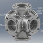
![Industrial steam jet ejector 3D CAD model showing inlet and discharge ports]()
What is an Ejector? Types, Parts, Datasheet, and Working Principles
![3D CAD model of industrial piping system showing color-coded piping classes and specifications.]()
Mastering the Piping Material Specification for Industrial Plant Design
![Industrial pig launcher and receiver station with quick-opening closure and bypass piping.]()
Design and Engineering of Pig Launchers and Receivers
![Close-up of an industrial dial pressure gauge mounted on a stainless steel pipe.]()
What is a Pressure Gauge and How Does It Work?
![3D cutaway diagram of an industrial ball valve showing internal components like the ball, stem, and seats.]()
What is a Ball Valve? Design, Types, and Engineering Standards