Table of Contents
Understanding the Difference Between ASME Sec VIII Div 1 vs Div 2
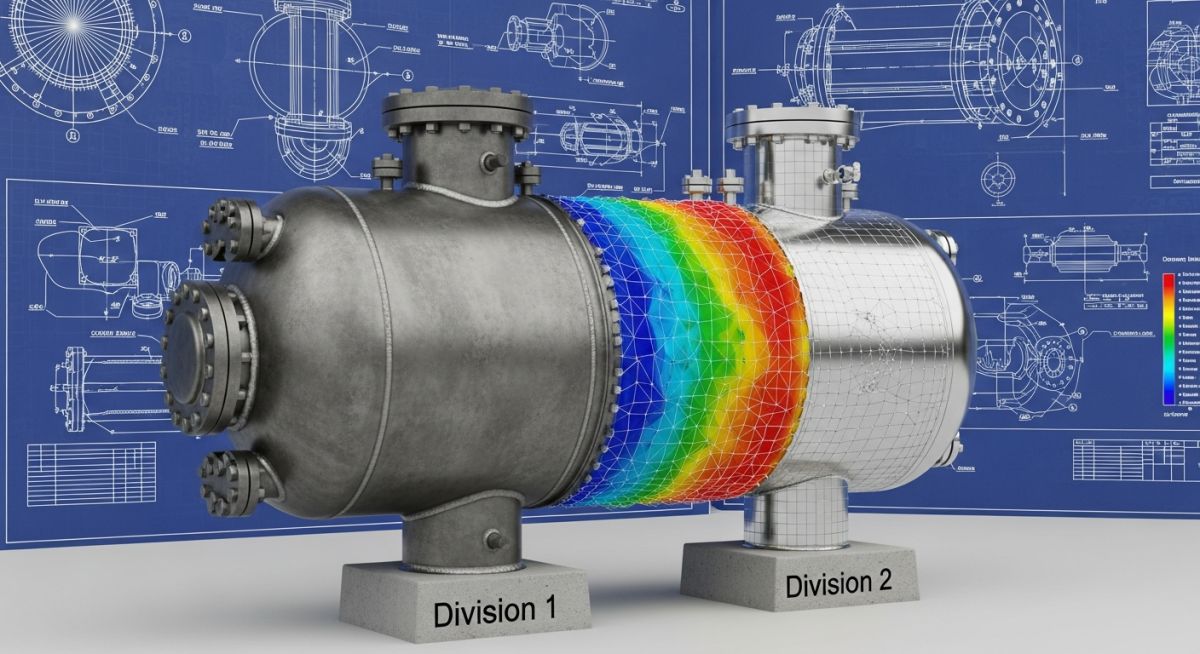
[ASME Section VIII Code Selection]: The choice between Division 1 and Division 2 dictates the design philosophy, safety factors, and overall manufacturing cost of a pressure vessel under ASME Section VIII rules.
When we design pressure vessels for oil refineries, chemical plants, and power generation facilities, we operate under the strict jurisdiction of the ASME Boiler and Pressure Vessel Code (BPVC) Section VIII. While Division 1 is the traditional workhorse of the industry, Division 2 represents an advanced, highly engineered alternative. The fundamental difference lies in how we balance design margins, material thickness, and engineering analysis.
Key Takeaways From My Field Experience
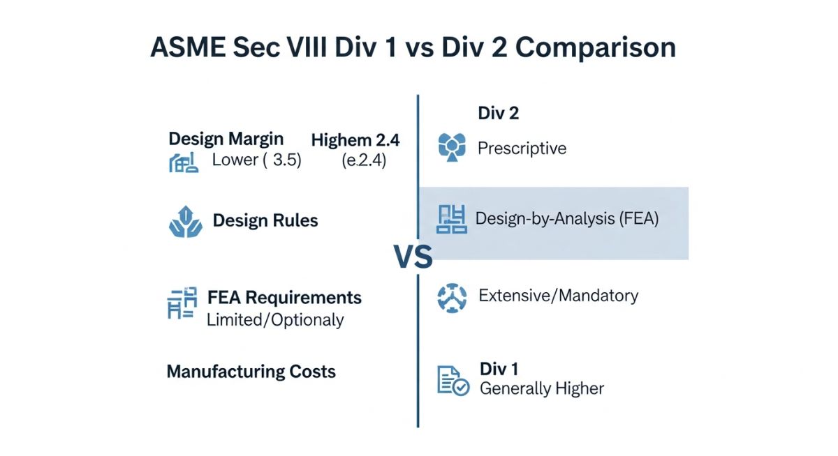
- Design Margins: Division 1 uses a conservative safety factor of 3.5 on ultimate tensile strength, while Division 2 Class 2 uses 2.4, allowing for thinner walls.
- Analysis Rigor: Division 1 relies on simple closed-form formulas. Division 2 requires detailed stress analysis, often utilizing Finite Element Analysis (FEA).
- Economic Break-Even: Division 2 typically becomes cost-effective for high-pressure vessels where material savings outweigh the increased engineering and inspection costs.
Key Design Philosophies of ASME Sec VIII Div 1 vs Div 2
[Pressure Vessel Design Methodologies]: Division 1 relies on conservative, simplified formulas based on membrane stress theory, whereas Division 2 permits advanced design-by-analysis methods using finite element analysis to optimize wall thickness.
To truly appreciate the difference, we must look at how each division calculates wall thickness. Division 1 is based on the Maximum Tensile Stress Theory. It assumes that as long as the calculated membrane stress does not exceed the allowable stress of the material, the vessel is safe. This approach does not explicitly calculate localized secondary or peak stresses; instead, it covers them using a high safety factor of 3.5.
In contrast, Division 2 is based on the Maximum Distortion Energy Theory (Von Mises Criterion). This division recognizes that materials can withstand higher loads if we perform a detailed stress categorization. We break down stresses into primary membrane, primary bending, secondary, and peak stresses. By analyzing these stresses individually, we can safely reduce the design margin to 2.4 (for Class 2) or even 3.0 (for Class 1), resulting in a significantly lighter vessel.
In my experience, engineers often select Division 1 for cyclic service because the initial design calculations are easier. However, Division 1 does not provide a formal fatigue analysis protocol. If your vessel experiences frequent pressure or temperature fluctuations, you must perform a fatigue evaluation. Division 2 has built-in, rigorous fatigue design curves that prevent catastrophic in-service failures.
Step-by-Step Thickness Calculation Comparison
Let us compare the required shell thickness for a high-pressure separator vessel using both codes.
Design Parameters:
- Design Pressure (P): 1,500 psi (10.34 MPa)
- Inside Radius (R): 30 inches (762 mm)
- Material: SA-516 Gr. 70 Carbon Steel
- Joint Efficiency (E): 1.0 (Fully Radiographed)
- Design Temperature: 100°F (38°C)
Material Properties from ASME Section II Part D:
- Specified Minimum Tensile Strength (UTS): 70,000 psi
- Specified Minimum Yield Strength (YS): 38,000 psi
1. ASME Section VIII Division 1 Calculation (UG-27):
The allowable stress (S) is the lesser of UTS / 3.5 or YS / 1.5:
S = min(70,000 / 3.5, 38,000 / 1.5) = min(20,000, 25,333) = 20,000 psi.
t = (P * R) / (S * E – 0.6 * P)
t = (1,500 * 30) / (20,000 * 1.0 – 0.6 * 1,500)
t = 45,000 / (20,000 – 900)
t = 45,000 / 19,100 = 2.356 inches (approx. 60 mm)
2. ASME Section VIII Division 2 Class 2 Calculation (Part 4.3.3):
The allowable stress (S) is the lesser of UTS / 2.4 or YS / 1.5:
S = min(70,000 / 2.4, 38,000 / 1.5) = min(29,166, 25,333) = 25,333 psi.
t = R * (exp(P / S) – 1) [Using the more precise shell formula]
t = 30 * (exp(1,500 / 25,333) – 1)
t = 30 * (exp(0.0592) – 1)
t = 30 * (1.0610 – 1)
t = 30 * 0.0610 = 1.830 inches (approx. 46.5 mm)
Thickness Reduction: 22.3% reduction in wall thickness! This translates directly to lower material weight, faster welding times, and reduced shipping costs.
Comparing ASME Sec VIII Div 1 vs Div 2 Specifications
[Code Specification Comparison]: A systematic evaluation of design margins, stress analysis requirements, and testing protocols reveals why Division 2 offers material savings at the expense of rigorous engineering overhead.
To help you make an informed decision during the front-end engineering design (FEED) phase of your project, I have compiled a comprehensive comparison table detailing the operational and administrative differences between these two divisions.
| Parameter | ASME Section VIII Division 1 | ASME Section VIII Division 2 |
|---|---|---|
| Design Margin (Tensile) | 3.5 on Ultimate Tensile Strength | 2.4 (Class 2) or 3.0 (Class 1) |
| Design Margin (Yield) | 1.5 on Yield Strength | 1.5 on Yield Strength |
| Design Methodology | Design-by-Formula (Closed-form equations) | Design-by-Analysis (FEA) & Design-by-Formula |
| Fatigue Analysis | Not explicitly addressed (No fatigue curves) | Mandatory screening; detailed analysis if required |
| User Design Specification (UDS) | Not required (User provides basic parameters) | Mandatory; must be certified by a Professional Engineer |
| Manufacturer’s Design Report | Not required (Form U-1 is filled out) | Mandatory; must be certified by a Professional Engineer |
| Nondestructive Examination (NDE) | Visual, spot, or fully radiographed options | Extensive, mandatory NDE (UT, RT, MT, PT) |
| Hydrostatic Test Pressure | 1.3 times Design Pressure | 1.43 (Class 1) or 1.25 (Class 2) times Design Pressure |
Technical Mapping & Specifications Matrix
This matrix maps the specific code sections and standards that govern the design, materials, and testing of vessels under both divisions.
| Entity / Standard | ASME Sec VIII Div 1 Reference | ASME Sec VIII Div 2 Reference |
|---|---|---|
| Material Allowable Stresses | ASME Section II Part D, Table 1A | ASME Section II Part D, Table 5A (Class 2) / Table 2A (Class 1) |
| External Pressure Design | Paragraph UG-28 | Part 4, Paragraph 4.4 |
| Opening Reinforcement | Paragraphs UG-36 through UG-42 | Part 4.5 (Area Replacement or Limit Analysis) |
| Toughness Requirements | Paragraphs UCS-66 through UCS-68 | Part 3, Paragraph 3.11 |
| Welding Qualifications | ASME Section IX | ASME Section IX + Part 6 Requirements |
Engineering Checklist for Code Selection
[Pressure Vessel Code Selection Checklist]: Engineers must systematically evaluate operating pressure, material costs, and cyclic loading conditions to determine the most economical and compliant ASME Section VIII division.
Before you sign off on a pressure vessel data sheet, run through this checklist to ensure you are not over-engineering a simple vessel or under-engineering a highly stressed, cyclic system.
Code Selection Decision Matrix
-
Is the design pressure above 3,000 psi (20.7 MPa)?
If yes, Division 2 is almost always more economical due to the massive reduction in wall thickness and associated welding volume.
-
Will the vessel experience cyclic thermal or pressure loading?
If yes, select Division 2 to utilize its rigorous fatigue analysis rules and prevent fatigue crack propagation.
-
Is the material a high-cost alloy (e.g., Duplex, Titanium, Hastelloy)?
If yes, the material savings from a thinner Division 2 shell will easily offset the higher engineering and FEA costs.
-
Are local fabricators certified for Division 2 (U2 Stamp)?
Verify that your chosen fabricator holds an active ASME U2 certificate. Not all shops that hold a U stamp can fabricate to Division 2.
-
Is a certified Professional Engineer (PE) available to sign off?
Division 2 requires a registered PE to certify both the User Design Specification (UDS) and the Manufacturer’s Design Report (MDR).
Field Case Study: Real-World Application
The Problem: Excessive Weight in a High-Pressure Hydrogen Separator
During a refinery expansion project in 2024, the initial design for a high-pressure hydrogen separator was specified under ASME Section VIII Division 1. The design pressure was 2,800 psi at 350°F. Using Division 1 rules, the calculated shell thickness was 4.25 inches, resulting in a total vessel weight of 145 metric tons. This weight exceeded the lifting capacity of the onsite crane and would have required a highly expensive, specialized crane rental, adding 180,000 to the installation budget.
The Outcome: Code Optimization to Division 2 Class 2
I stepped in and performed a comparative analysis using Division 2 Class 2 rules. By utilizing the lower design margin of 2.4 and performing a detailed Finite Element Analysis (FEA) on the nozzles and transitions, we reduced the required shell thickness to 3.125 inches. This reduced the total vessel weight to 102 metric tons—a 30% weight reduction. The vessel was safely installed using the standard onsite crane, saving the project 180,000 in crane rental fees and over 95,000 in raw material costs.
This case study demonstrates that the decision between Division 1 and Division 2 is not just about compliance; it directly impacts logistics, installation, and overall project feasibility.
Frequently Asked Engineering Questions
[ASME Code FAQ Directory]: This technical reference addresses critical questions regarding design margins, stamping, and engineering requirements for Section VIII vessels.
What is the exact break-even pressure for choosing Division 2 over Division 1?
Can a Division 1 vessel be stamped with a Division 2 stamp?
What is the difference between Division 2 Class 1 and Class 2?
Is Finite Element Analysis (FEA) mandatory for all Division 2 vessels?
Why are the hydrostatic test factors different between the two divisions?
Who is responsible for certifying the User Design Specification (UDS)?
===
Complete Course on
Piping Engineering
Check Now
Key Features
- 125+ Hours Content
- 500+ Recorded Lectures
- 20+ Years Exp.
- Lifetime Access
Coverage
- Codes & Standards
- Layouts & Design
- Material Eng.
- Stress Analysis

📚 Recommended Resources: ASME Sec VIII Div 1 vs Div 2
Read these Guides


Related posts:
![Professional land surveyor using a total station for a topographic survey in an open field]()
Understanding Land Mapping and the True Topographic Survey Cost
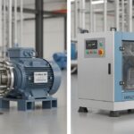
![Side-by-side comparison of an industrial centrifugal pump and a rotary screw compressor.]()
What is the Difference Between Pump and Compressor Systems?
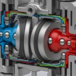
![Cutaway 3D render of an industrial air-operated double-diaphragm pump showing internal components.]()
Understanding Diaphragm Pumps: A Comprehensive Guide for Industrial Plants
![A metallic pipe sleeve embedded in a concrete wall with a carrier pipe passing through it.]()
What is a Pipe Sleeve and How Does It Protect Piping?
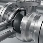
![Industrial stainless steel swing check valve installed in a pipeline with a flow direction arrow.]()
What are Check Valves? Types of Check Valves & Their Symbols
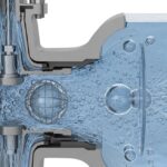
![Cross-section diagram of a control valve showing cavitation bubbles and flashing liquid.]()
How to Prevent Control Valve Cavitation and Flashing Damage