Table of Contents
What is Cladded Pipe? Difference Between Clad and Lined Pipe
In my 20 years of managing piping systems in offshore oil platforms and chemical processing plants, I have seen many engineers make costly mistakes when selecting corrosion-resistant piping. Choosing between a metallurgically bonded clad pipe and a mechanically bonded lined pipe is not just a matter of cost. It is a decision that impacts the structural integrity, fatigue life, and safety of your entire facility. Let me share the practical realities of these systems, how they behave under thermal cycling, and why weld overlay cladding is often the ultimate insurance policy for high-pressure, high-temperature environments.
Key Takeaways for Piping Engineers:
- Clad pipes provide a continuous metallurgical bond, making them ideal for high-vacuum and high-temperature applications.
- Lined pipes offer a cost-effective mechanical bond but are susceptible to collapse under vacuum and liner wrinkling during bending.
- Weld overlay cladding (CRA) is the preferred method for complex geometries, fittings, and flange faces.
Key Engineering Differences in Clad vs Lined Pipe Systems
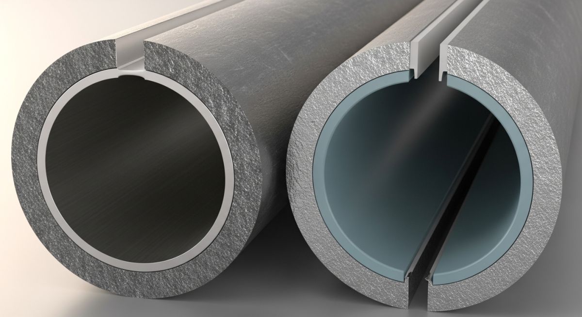
To understand the fundamental difference in clad vs lined pipe, we must look at the interface between the backing material (typically carbon steel or low-alloy steel) and the Corrosion Resistant Alloy (CRA) layer. In a cladded pipe, the bond is metallurgical. This means the atoms of the backing steel and the CRA layer interdiffuse at the interface, creating a single, continuous metallic structure. This is achieved through hot rolling, explosive bonding, or weld overlay cladding.
Conversely, a mechanically lined pipe relies on a tight mechanical fit. The CRA liner is inserted inside the carbon steel outer pipe, and the assembly is expanded hydraulically or mechanically. There is no atomic bonding at the interface; the liner is held in place purely by residual compressive stresses.
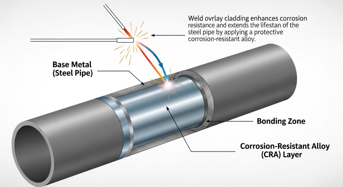
Weld Overlay Cladding (CRA Overlay)
Weld overlay cladding is a process where a corrosion-resistant alloy is deposited onto the surface of a base metal via arc welding. In my project experience, we specify weld overlay for complex geometries like tees, elbows, and valve bodies where plate cladding is impossible. Common welding processes include Gas Tungsten Arc Welding (GTAW), Gas Metal Arc Welding (GMAW), and Electroslag Strip Cladding. The critical parameter here is controlling the iron dilution from the base metal into the overlay layer to maintain corrosion resistance.
Design Calculations and Stress Limitations
When designing clad piping systems under ASME B31.3, the minimum wall thickness of the base pipe is calculated using the standard pressure design formula:
Where:
P = Internal design gage pressure
D = Outside diameter of the pipe
S = Allowable stress value for the base material
E = Quality factor
W = Weld joint strength reduction factor
Y = Coefficient from Table 304.1.1
According to ASME B31.3 Chapter VIII, the structural strength of the cladding layer is typically neglected in pressure design calculations unless the metallurgical bond is fully qualified and the cladding material’s strength is explicitly included. Therefore, the cladding thickness (usually 2.0 mm to 4.0 mm) is treated as an additional corrosion allowance.
Field Warning:
Never use mechanically lined pipes in high-vacuum services or systems subject to rapid depressurization. The vacuum or sudden pressure drop can cause the mechanical liner to collapse inward, completely blocking the flow path and leading to catastrophic system failure.
| Parameter | Clad Pipe (Metallurgical) | Lined Pipe (Mechanical) | Weld Overlay (CRA) |
|---|---|---|---|
| Bonding Type | Atomic / Metallurgical | Mechanical / Friction Fit | Fused Weld Deposit |
| Vacuum Resistance | Excellent (No separation) | Poor (Risk of collapse) | Excellent (No separation) |
| Thermal Cycling Limit | High (Up to 400°C) | Moderate (Risk of buckling) | High (Up to 450°C) |
| Relative Cost | High | Medium-Low | High (Best for fittings) |
| Common Standards | API Spec 5LD, ASTM A263 | API Spec 5LD | ASME Sec IX, API 5LD |
| Entity / Acronym | Description | Physical Parameter / Limit | Standard Reference |
|---|---|---|---|
| CRA | Corrosion Resistant Alloy | Typically 3.0 mm min thickness | API Spec 5LD |
| UNS N06625 | Alloy 625 (Nickel-Chromium) | Max Iron dilution < 5% or 10% | ASME Sec II Part D |
| UT | Ultrasonic Testing | 100% coverage for bond check | ASTM A578 |
| PMI | Positive Material Identification | Verifies alloy composition | API RP 578 |
Site Inspection Protocols for Clad vs Lined Pipe Installations
During field installation, the integrity of the corrosion-resistant barrier must be protected. Any damage to the internal CRA layer can expose the carbon steel backing to aggressive process fluids, leading to rapid localized corrosion. The following checklist outlines the critical verification steps that I enforce during site inspections.
Field Quality Control Checklist:
-
✔
Bond Integrity: Verify metallurgical bond integrity using Ultrasonic Testing (UT) in accordance with ASTM A578. -
✔
PMI Verification: Perform Positive Material Identification (PMI) on the CRA layer to confirm chemical composition (especially Iron dilution limits in weld overlays, typically kept below 5%). -
✔
End Seal Inspection: Inspect mechanical liner ends for proper seal welding or flange face overlay to prevent corrosive fluid from reaching the carbon steel backing. -
✔
Helium Leak Testing: Conduct helium leak testing on the annulus of mechanically lined pipes to ensure no pinhole leaks exist in the liner. -
✔
Overlay Thickness: Ensure weld overlay thickness meets the minimum design requirement (typically 3.0 mm minimum finished thickness).
Field Case Study: Real-World Application
The Problem:
An offshore gas production platform experienced repeated failures of mechanically lined carbon steel piping handling wet sour gas (containing high hydrogen sulfide and carbon dioxide) at 120 degrees Celsius. During shutdown cycles, the rapid depressurization caused the mechanical liner to collapse, restricting flow and allowing corrosive fluids to bypass the liner, leading to severe localized pitting of the carbon steel outer shell.
The Solution & Outcome:
I recommended replacing the failed mechanically lined sections with metallurgically clad pipes manufactured via hot-roll bonding, with all field joints completed using Alloy 625 weld overlay. The metallurgical bond completely eliminated the risk of liner collapse under depressurization. After five years of continuous service, ultrasonic inspections showed zero bond degradation and zero corrosion propagation, saving the operator millions in unplanned downtime.
Direct Recommendation: Always specify metallurgically clad pipe or weld overlay for high-pressure sour gas services subject to transient pressure drops or vacuum conditions.
Frequently Asked Engineering Questions
What is the primary difference between clad and lined pipe?
How does weld overlay cladding prevent corrosion?
Can mechanically lined pipes be bent on site?
What are the maximum temperature limits for clad vs lined pipes?
How is the iron dilution controlled in weld overlay cladding?
Which standards govern the design and manufacture of clad pipes?
======
Complete Course on
Piping Engineering
Check Now
Key Features
- 125+ Hours Content
- 500+ Recorded Lectures
- 20+ Years Exp.
- Lifetime Access
Coverage
- Codes & Standards
- Layouts & Design
- Material Eng.
- Stress Analysis

📚 Recommended Resources: clad vs lined pipe
Read these Guides


Related posts:
![Industrial hydrogen compression system facility with stainless steel piping and modern compressor equipment.]()
Mastering Hydrogen Compression Systems: Engineering Design, Selection, and Safety
![Modern industrial hydrogen storage facility with high-pressure tanks and clean energy infrastructure.]()
Hydrogen Storage Technologies: A Comprehensive Engineering and Selection Guide
![Modern industrial hydrogen storage facility with stainless steel tanks and safety piping.]()
Mastering Hydrogen Safety in Industrial Facilities: Engineering and Design Guide
![Conceptual illustration of global hydrogen transportation methods including pipelines, trucks, and ships.]()
How to Select and Design Hydrogen Transportation Methods Safely
![Conceptual illustration comparing grey, blue, and green hydrogen production facilities and their environmental impact.]()
Green vs Blue vs Grey Hydrogen: Complete Engineering Comparison Guide
![Modern green hydrogen production plant powered by solar and wind energy.]()
Green Hydrogen Production Process and Industrial Plant Design Guide