Table of Contents
What is HVAC Piping? Types, Materials, and Standards
In my 20 years of piping engineering, I have seen many projects succeed or fail based on the design of their hydronic and refrigerant networks. HVAC piping is the circulatory system of any modern building. If you select the wrong material, miscalculate thermal expansion, or ignore code-mandated velocity limits, you will face system-wide failures. Whether it is a chilled water loop for a data center or a high-pressure steam line for an industrial facility, understanding the physical properties of your piping media is the first step toward building a reliable system.
Throughout my career, I have guided field teams through complex installations where thermal stress threatened to tear apart welded joints. By adhering strictly to established standards and selecting materials based on fluid chemistry and temperature limits, we can prevent these costly field failures. Let us explore the core types, materials, and standards that define modern HVAC piping design.
Key Engineering Takeaways
- Material Matching: Copper remains the standard for refrigerant lines, while carbon steel dominates large-bore hydronic loops.
- Code Compliance: Always design building service lines to ASME B31.9 and refrigerant lines to ASME B31.5.
- Velocity Limits: Keep hydronic water velocity below 8 feet per second to prevent erosion-corrosion and excessive noise.
- Thermal Management: Incorporate expansion loops to absorb dimensional changes caused by temperature swings.
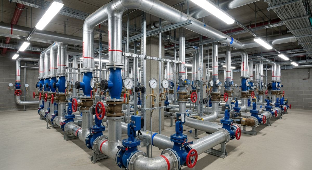
What is HVAC Piping? Core Engineering Principles
HVAC Piping Design: The systematic selection of pipe schedules, insulation thicknesses, and routing configurations to safely contain and transport thermal media while minimizing pressure drop and thermal losses in compliance with ASHRAE guidelines.
To design an efficient HVAC piping system, you must first categorize the system by its fluid medium. The four primary categories are hydronic (chilled and hot water), steam, condensate drainage, and refrigerant piping. Each system operates under distinct thermodynamic and physical constraints.
1. Hydronic Piping Systems
Hydronic systems use water or water-glycol mixtures as the heat transfer fluid. Chilled water loops typically operate between 40 degrees Fahrenheit and 55 degrees Fahrenheit, while heating water loops operate from 120 degrees Fahrenheit up to 200 degrees Fahrenheit. The primary design challenge here is balancing flow rates and managing pressure drops.
2. Refrigerant Piping Systems
Refrigerant piping connects compressors, condensers, and evaporators. These systems operate under high pressures and must transport both liquid and gaseous refrigerant along with compressor oil. Because of these dual-phase requirements, line sizing is critical. If the pipe is too large, refrigerant velocity drops, and oil will not return to the compressor, leading to mechanical failure.
Engineering Calculations: Friction Loss and Thermal Expansion
Friction loss in hydronic piping is calculated using the Darcy-Weisbach equation: head loss equals the friction factor multiplied by the ratio of pipe length to inside diameter, multiplied by the velocity squared divided by two times the acceleration due to gravity. In practice, engineers often use the Hazen-Williams equation for water systems: pressure drop per hundred feet equals 0.2083 multiplied by the ratio of 100 over the roughness coefficient raised to the power of 1.85, multiplied by flow rate in gallons per minute raised to the power of 1.85 divided by the inside pipe diameter in inches raised to the power of 4.8655.
Thermal expansion is another critical calculation. The change in pipe length is calculated using the formula: change in length equals the original length multiplied by the material coefficient of thermal expansion multiplied by the temperature difference. For carbon steel, the coefficient is approximately 0.0000065 inches per inch per degree Fahrenheit, whereas copper is significantly higher at 0.0000093 inches per inch per degree Fahrenheit. Failure to design adequate expansion loops will result in high structural stresses on anchors and equipment nozzles.
| Material | Standard Specification | Temperature Range | Typical HVAC Application | Joining Method |
|---|---|---|---|---|
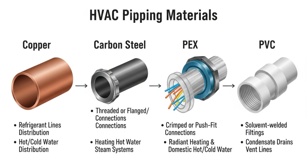
| Copper (Type L & K) | ASTM B88 | -40°F to 400°F | Refrigerant lines, domestic water, small hydronic runs | Brazing, Soldering, Press-connect |
| Carbon Steel (Sch 40/80) | ASTM A53 Grade B | -20°F to 800°F | Large chilled water, hot water, steam, condenser loops | Butt-welding, Threaded, Grooved mechanical |
| Stainless Steel (304/316) | ASTM A312 | -325°F to 1000°F | Corrosive environments, cleanrooms, high-temp steam | TIG welding, Press-fit |
| PP-R / PP-RCT (Plastic) | ASTM F2389 | 0°F to 180°F | Chilled water, condenser water, geothermal loops | Heat fusion welding |
| System Service | Governing Code | Velocity Limit (fps) | Corrosion Allowance | Recommended Insulation |
|---|---|---|---|---|
| Chilled Water (CHW) | ASME B31.9 | 4.0 to 8.0 | 0.0625 inches | Closed-cell elastomeric foam |
| Condenser Water (CDW) | ASME B31.9 | 5.0 to 10.0 | 0.1250 inches | Not typically insulated (unless outdoor) |
| Low-Pressure Steam (LPS) | ASME B31.1 / B31.9 | 80.0 to 120.0 | 0.0625 inches | Fiberglass mineral wool |
| Refrigerant (REF) | ASME B31.5 | Gas: 15-50 / Liquid: 2-4 | 0.0000 inches (non-corrosive) | Elastomeric foam (suction line only) |
HVAC Piping Installation Field Checklist
Pre-Commissioning Verification: A structured quality assurance protocol executed prior to system charging to verify structural support integrity, pressure test compliance, and insulation continuity under ASME B31.9.
Before you hand over any HVAC piping system to the commissioning agent, you must verify that the physical installation matches the design drawings and engineering specifications. Use this checklist on-site to prevent catastrophic startup failures.
Field Verification Checkpoints
-
Hydrostatic Pressure Testing: Verify that the hydronic piping has been pressure tested at 1.5 times the design working pressure for a minimum of 4 hours in accordance with ASME B31.9.
-
Hanger and Support Spacing: Confirm that pipe hangers are spaced according to MSS SP-58 standards. Ensure that insulated lines use high-density inserts with vapor barriers to prevent crushing.
-
Air Venting and Drainage: Check that manual or automatic air vents are installed at all high points of the hydronic loop, and drain valves are present at all low points.
-
Expansion Loop Clearance: Inspect all expansion loops and joints. Ensure that shipping bars have been removed and that the piping has room to expand without hitting structural elements.
-
Flushing and Chemical Treatment: Verify that the system has been thoroughly flushed with clean water and treated with corrosion inhibitors before being put into continuous service.
What is HVAC Piping? Case Study
HVAC Piping Remediation: The forensic analysis and physical modification of a failing hydronic loop to resolve severe thermal expansion stress and flow imbalances.
The Problem: Chilled Water Riser Joint Failures
On a 15-story commercial office tower project, the field team reported recurring leaks at the main 8-inch chilled water riser joints on floors 4 and 8. The system used Schedule 40 carbon steel piping with grooved mechanical couplings.
Upon inspection, I discovered that the original design had omitted expansion loops, assuming the grooved couplings would absorb all axial movement. However, because the pipe anchors were improperly placed, the thermal contraction during the 42°F chilled water cycle pulled the joints past their maximum deflection limits, tearing the gaskets.
The Outcome: Redesign and Stress Relief
I performed a thermal stress analysis and redesigned the riser support system. We installed a massive U-shaped expansion loop at the midpoint of the riser (floor 7) and anchored the pipe securely at the basement and the roof.
We replaced the damaged grooved couplings with flexible expansion joints rated for the system’s dynamic movement. After re-testing the system at 150 psi for 4 hours, the leaks were completely resolved, and the system has operated without a single failure for over five years.
My recommendation for any multi-story hydronic installation is simple: never rely solely on standard mechanical couplings to absorb thermal expansion. Always calculate the actual physical movement and design dedicated expansion loops or bellows-type expansion joints to handle the load.
HVAC Piping Frequently Asked Questions
HVAC Piping FAQ: A technical reference addressing common design queries, material limitations, and code compliance requirements for hydronic and refrigerant systems.
What is the difference between Type K, Type L, and Type M copper pipes in HVAC?
Why is carbon steel preferred over copper for large HVAC piping systems?
Which ASME code governs HVAC piping design?
How do you prevent galvanic corrosion in HVAC piping?
What is the purpose of a balancing valve in a hydronic piping loop?
Can plastic piping like PP-R be used for all HVAC applications?
===FAQ_BLOCK===
Complete Course on
Piping Engineering
Check Now
Key Features
- 125+ Hours Content
- 500+ Recorded Lectures
- 20+ Years Exp.
- Lifetime Access
Coverage
- Codes & Standards
- Layouts & Design
- Material Eng.
- Stress Analysis

📚 Recommended Resources: HVAC piping
Read these Guides
🎓 Advanced Training


Related posts:
![A mechanical sucker rod pumpjack operating in an oil field at sunset]()
What is Sucker Rod Pump System in Oil Production?
![Piping material engineer reviewing technical specifications on a tablet in an industrial plant.]()
How a Piping Material Engineer Drives Industrial Project Success
![Industrial refinery plant showing various types of static equipment]()
What is Static Equipment? Types and List of Static Equipments
![Side-by-side comparison of industrial process piping and power plant steam piping systems.]()
Differences Between ASME B31.3 and B31.1: B31.3 vs B31.1
![Large industrial steel storage tank under construction with cranes and scaffolding]()
Storage Tank Construction Method Statement: Step-by-Step Engineering Guide
![Cutaway diagram of a globe control valve highlighting the internal valve trim components]()
What is a Valve Trim? Types, Components, and Selection


