Table of Contents
What is Cryogenic Piping and How to Design It
During my 20 years in the piping engineering field, I have seen many systems fail due to a lack of respect for extreme cold. I remember a liquid nitrogen line commissioning where the thermal contraction calculation was off by just 15 percent. When the sub-zero fluid hit the line, the resulting contraction sheared a heavy-duty anchor bolt clean off its pedestal. That day cemented a core lesson for me: designing cryogenic piping is not just about keeping fluids cold; it is about managing the immense physical forces generated when materials shrink under extreme thermal gradients.
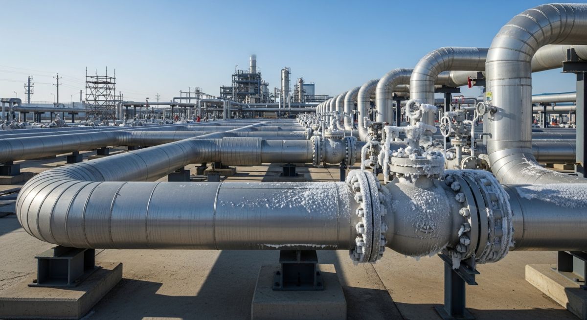
When you deal with liquefied natural gas (LNG) at minus 162 degrees Celsius, or liquid helium at minus 269 degrees Celsius, standard carbon steel becomes as brittle as glass. A single impact can cause catastrophic shattering. To prevent this, we must look to specialized metallurgy, advanced insulation systems, and highly engineered pipe supports. This guide details the exact engineering principles, material selections, and support designs required to build safe, high-performance systems.
- The fundamental physics of cryogenic temperatures and their impact on piping materials.
- How to select the correct metallic alloys to prevent low-temperature brittle fracture.
- The mechanics of thermal contraction and how to calculate precise dimensional changes.
- Design principles for vacuum-jacketed piping and cold shoe supports.
- Field-tested verification steps to ensure safe commissioning and long-term operation.
Designing Cryogenic Piping for Extreme Thermal Contraction
The primary challenge in cryogenic piping design is thermal contraction. While hot piping systems expand, cryogenic lines contract significantly when transitioning from ambient installation temperatures to sub-zero operating conditions. If this contraction is restricted, it generates massive tensile stresses that can easily rupture welds, bend structural steel, or destroy connected equipment nozzles.
To calculate the linear thermal contraction of a piping run, we use the following fundamental engineering formula:
Where:
• dL is the total change in pipe length (mm)
• L is the initial length of the piping run at ambient temperature (m)
• alpha is the mean coefficient of thermal expansion/contraction for the specific material (mm/m-°C)
• dT is the temperature difference between installation and operation (°C)
Let us look at a practical example. Consider a 100-meter run of ASTM A312 TP316L stainless steel piping being cooled from an ambient installation temperature of 20 degrees Celsius down to a liquid nitrogen operating temperature of minus 196 degrees Celsius. The mean coefficient of thermal contraction for 316L stainless steel over this range is approximately 14.7 x 10^-6 m/m-K.
dL = 100 * 14.7e-6 * -216
dL = -0.317 meters = -317 mm
This calculation reveals that the piping run will shrink by nearly 32 centimeters! If we do not design adequate flexibility into this system using expansion loops, offsets, or bellows, the resulting thermal stress will exceed the allowable limits defined by ASME B31.3, leading to mechanical failure.
Managing Heat Leak and Thermal Insulation
Another major design factor is heat leak. Any heat entering the system from the surrounding environment vaporizes the cryogenic liquid, causing pressure build-up and product loss. To minimize this, we use two primary insulation methods:
- Vacuum Jacketed Piping (VJP): This consists of an inner process pipe surrounded by an outer jacket pipe. The annular space is evacuated to a high vacuum and filled with multi-layer insulation (MLI) to eliminate convective and radiative heat transfer. This is the gold standard for liquid helium and liquid hydrogen.
- Mechanical Insulation: For less demanding applications like low-pressure liquid nitrogen or LNG, we often use thick layers of cellular glass or high-density polyurethane foam (HDPF) wrapped in a robust vapor barrier to prevent moisture ingress.
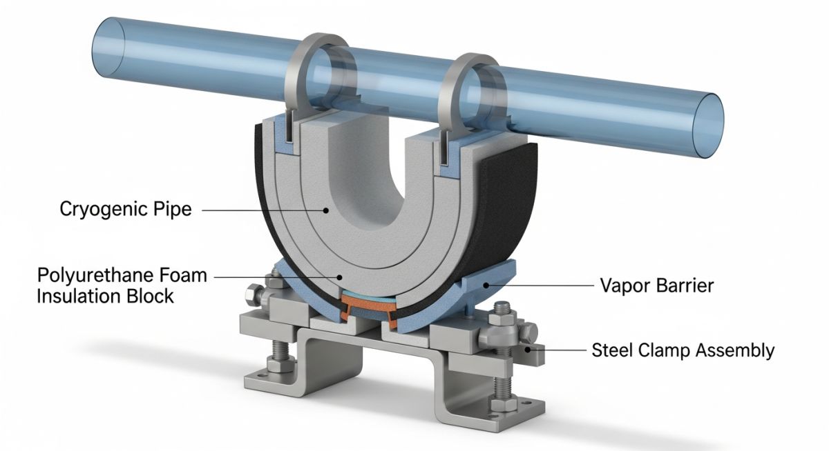
The Role of Specialized Cold Shoe Supports
We cannot support a cryogenic pipe directly on a steel beam. If we did, the extreme cold would travel down the support, freezing the structural steel and causing it to undergo a ductile-to-brittle transition. This phenomenon, known as “cold bridging,” can cause structural collapse.
To prevent this, we use specialized cold shoe supports. These supports utilize a load-bearing insulating block made of high-density polyurethane foam, Micarta, or laminated wood. This block is sandwiched between the pipe clamp and the structural attachment, effectively isolating the cold pipe from the warm support structure while still allowing the pipe to slide or guide as required by the stress analysis.
Selecting Materials for Cryogenic Piping Systems
Selecting the right material is the foundation of safe cryogenic engineering. Standard carbon steels (like ASTM A106) lose their impact toughness rapidly below minus 29 degrees Celsius. For cryogenic services, we must use materials with a face-centered cubic (FCC) crystal structure, which do not exhibit a ductile-to-brittle transition temperature.
The table below outlines the standard metallic alloys used in cryogenic services, along with their Minimum Design Metal Temperature (MDMT) and typical industrial applications.
| Material Specification | Common Name | MDMT (°C) | Key Application |
|---|---|---|---|
| ASTM A312 TP316L | 316L Stainless Steel | -254 | Liquid Nitrogen, LNG, Liquid Oxygen piping |
| ASTM A312 TP304L | 304L Stainless Steel | -196 | Standard LNG and industrial gas distribution |
| ASTM A333 Grade 8 | 9% Nickel Steel | -196 | Large-diameter LNG storage tank piping |
| ASTM B209 Alloy 5083 | Aluminum-Magnesium | -273 | Cryogenic heat exchangers, cold boxes |
| Invar (Fe-36Ni) | 36% Nickel-Iron | -273 | Ultra-low expansion liquid helium lines |
To ensure all components of a cryogenic system are compatible, we map the core technical entities, structural acronyms, and physical parameters to their governing standards.
| Entity / Acronym | Governing Standard | Physical Parameter | Engineering Role |
|---|---|---|---|
| VJP | ASME B31.3 Chapter IX | Vacuum level < 10^-4 Torr | Eliminates convective heat transfer |
| Cold Shoe | MSS SP-58 | Compressive strength > 10 MPa | Prevents cold bridging to structural steel |
| Thermal Bowing | ASME B31.3 App. F | Differential temperature gradient | Causes pipe warping during cool-down |
| ASTM A320 L7 | ASTM A320 | Charpy V-Notch Impact at -101°C | High-strength bolting for low-temp flanges |
Field Verification for Cryogenic Piping Installations
Commissioning a cryogenic system is a high-risk operation. If a single support is locked or an insulation barrier is compromised, the system can fail violently upon cool-down. I have developed this field verification checklist over two decades of supervising plant start-ups to ensure no critical detail is missed.
-
Verify Material Traceability: Ensure 100% Positive Material Identification (PMI) has been performed on all process lines to confirm no carbon steel components were accidentally installed.
-
Inspect Cold Shoe Alignment: Confirm that all cold shoe supports are centered on their structural steel pedestals, allowing adequate clearance for the calculated thermal contraction movement.
-
Check Vacuum Jacket Integrity: For vacuum-jacketed lines, verify that the vacuum pressure is stable and below the maximum allowable limit (typically 10^-4 Torr) using a calibrated vacuum gauge.
-
Validate Vapor Barrier Continuity: Ensure the polyurethane or cellular glass insulation vapor barrier is completely sealed with no tears, punctures, or gaps that could allow moisture to enter and freeze.
-
Confirm Spring Support Presets: Verify that all variable and constant spring hangers are set to their correct “cold” preset positions and that travel stops have been removed.
-
Perform Low-Point Drain Checks: Ensure all low-point drains are clear of moisture before introducing cryogenic fluids to prevent ice plugs from forming and blocking the line.
-
Verify Flange Bolting Torque: Confirm that all cryogenic flange connections utilize ASTM A320 L7 bolts and have been torqued to specification using a calibrated torque wrench.
Field Case Study: Real-World Application
During the commissioning of a major LNG import terminal, a 12-inch liquid LNG transfer line operating at minus 162 degrees Celsius experienced severe thermal bowing. The pipe lifted off three consecutive intermediate supports, causing the entire thermal load to transfer directly to the inlet nozzle of a primary storage tank. The nozzle stress exceeded the allowable limit by 240 percent, risking a catastrophic tank shell rupture.
Our engineering team intervened and discovered that the cold shoe slide plates had been installed backward, locking the support in place and preventing lateral movement. We immediately depressurized the system, replaced the locked supports with low-friction PTFE slide plates, and installed high-density polyurethane foam (HDPF) cold shoes. We re-modeled the system in CAESAR II to ensure the thermal movements were guided rather than restricted. Upon re-commissioning, the line contracted smoothly, nozzle stresses dropped to 45 percent of the allowable limit, and the system has operated safely for over eight years.
This case highlights why precise support design and field verification are non-negotiable. A simple installation error on a slide plate completely altered the stress profile of the piping system, demonstrating that cryogenic engineering requires absolute attention to detail from the design office to the construction site.
Frequently Asked Engineering Questions
Why is carbon steel prohibited in cryogenic piping systems?
What is the purpose of a cold shoe support?
How does vacuum-jacketed piping minimize heat leak?
What is thermal bowing and how do we prevent it?
Which ASME code governs cryogenic piping design?
Why is moisture control critical during cryogenic commissioning?
===FAQ_BLOCK===

Complete Course on
Piping Engineering
Check Now
Key Features
- 125+ Hours Content
- 500+ Recorded Lectures
- 20+ Years Exp.
- Lifetime Access
Coverage
- Codes & Standards
- Layouts & Design
- Material Eng.
- Stress Analysis
📚 Recommended Resources: cryogenic piping
Read these Guides
🎓 Advanced Training


Related posts:
![A mechanical sucker rod pumpjack operating in an oil field at sunset]()
What is Sucker Rod Pump System in Oil Production?
![Piping material engineer reviewing technical specifications on a tablet in an industrial plant.]()
How a Piping Material Engineer Drives Industrial Project Success
![Industrial refinery plant showing various types of static equipment]()
What is Static Equipment? Types and List of Static Equipments
![Side-by-side comparison of industrial process piping and power plant steam piping systems.]()
Differences Between ASME B31.3 and B31.1: B31.3 vs B31.1
![Large industrial steel storage tank under construction with cranes and scaffolding]()
Storage Tank Construction Method Statement: Step-by-Step Engineering Guide
![Cutaway diagram of a globe control valve highlighting the internal valve trim components]()
What is a Valve Trim? Types, Components, and Selection


