What is a Pulsation Dampener and How Does It Work
In my 20 years of designing piping systems for oil and gas facilities, I have stood next to reciprocating pumps that shook the entire concrete foundation. The culprit is almost always the same: uncontrolled pressure surges. When a positive displacement pump operates, it does not deliver a smooth, continuous stream of fluid. Instead, it pushes fluid in distinct pulses. Without intervention, these pulses create severe acoustic resonance, leading to pipe fatigue, loose supports, and catastrophic weld failures.
That is where a pulsation dampener becomes your system’s lifesaver. By absorbing these high-frequency pressure spikes, this device acts as a hydraulic shock absorber. In this guide, I will share my hands-on field experience to explain how these units work, how to size them, and how to select the right type for your specific process conditions.
- The fundamental physics behind pressure surge absorption.
- How to calculate the required volume for a bladder-type dampener.
- Key differences between active, passive, and clean-in-place designs.
- Field-tested installation and pre-charging protocols to prevent bladder rupture.
Complete Course on
Piping Engineering
Check Now
Key Features
- 125+ Hours Content
- 500+ Recorded Lectures
- 20+ Years Exp.
- Lifetime Access
Coverage
- Codes & Standards
- Layouts & Design
- Material Eng.
- Stress Analysis
How a Pulsation Dampener Protects Piping Systems
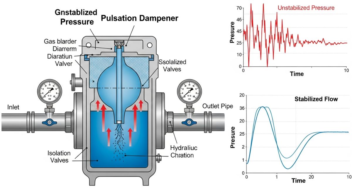
To understand the mechanics, we must look at the pump’s discharge cycle. A reciprocating pump plunger forces fluid into the discharge line during its forward stroke, causing a rapid pressure rise. During the suction stroke, the flow stops or reverses slightly, causing a pressure drop. This cyclic behavior generates a high-amplitude pressure wave.
A gas-charged pulsation dampener contains a flexible elastomer bladder filled with pressurized nitrogen gas. Because gas is highly compressible compared to liquids, it acts as a pneumatic spring. When the pump discharges fluid, the pressure spike forces liquid into the dampener vessel, compressing the nitrogen bladder. During the low-pressure phase of the pump cycle, the compressed gas expands, pushing the stored fluid back into the main line. This continuous storage and release cycle smooths out the flow velocity profile.
The Mathematical Sizing Formula
Sizing a dampener is not a guessing game. Under-sizing leads to rapid bladder wear and high residual pulsation, while over-sizing wastes valuable space and capital. In my practice, I use the standard gas laws to determine the minimum required volume:
Where:
- V_p = Required dampener volume (Liters)
- V_s = Pump stroke volume (Liters per stroke), calculated as piston area multiplied by stroke length.
- K = Pump constant based on the number of cylinders (e.g., 0.60 for simplex single-acting, 0.25 for duplex, 0.05 for triplex).
- P_m = Mean operating system pressure (bara).
- P_p = Nitrogen pre-charge pressure (bara), which must be set relative to the system operating pressure.
Never use compressed air or oxygen to pre-charge a pulsation dampener. If the process fluid contains hydrocarbons, compressing oxygen inside the vessel can trigger a spontaneous, catastrophic explosion. Always use high-purity nitrogen gas (minimum 99.99% purity) for pre-charging.
Design and Stress Limitations
When specifying these vessels under ASME B31.3 Process Piping, you must account for cyclic fatigue. The vessel shell must be rated for the maximum allowable working pressure (MAWP) of the system. Furthermore, the elastomer bladder material must be carefully matched to the process chemistry and temperature limits. For instance, Viton (FKM) is excellent for high-temperature hydrocarbons but will fail rapidly in low-temperature water systems.
Sizing Parameters for Pulsation Dampener Selection
The table below outlines the standard engineering parameters I use during the front-end engineering design (FEED) phase to select the appropriate dampener configuration based on pump configuration and process conditions.
| Pump Configuration | Pump Constant (K) | Recommended Pre-charge % | Elastomer Material | Temperature Range (°C) |
|---|---|---|---|---|
| Simplex Single-Acting | 0.60 | 60% of Min Pressure | EPDM / NBR | -30 to 120 |
| Duplex Double-Acting | 0.25 | 70% of Min Pressure | Viton (FKM) | -15 to 200 |
| Triplex Single-Acting | 0.05 | 80% of Min Pressure | PTFE (Teflon) | -100 to 260 |
| Quintuplex Single-Acting | 0.02 | 85% of Min Pressure | NBR (Nitrile) | -40 to 100 |
Technical Mapping and Specifications Matrix
To ensure your design complies with international safety regulations, refer to this mapping of core technical entities and their corresponding design codes.
| Technical Entity | Acronym | Physical Parameter | Standard Reference |
|---|---|---|---|
| Maximum Allowable Working Pressure | MAWP | Pressure (bar / psi) | ASME Sec VIII Div 1 |
| Reciprocating Pump Standards | API 674 | Pulsation Limits (1.5% peak-to-peak) | API Standard 674 |
| Controlled Volume Pumps | API 675 | Flow Accuracy & Linearity | API Standard 675 |
| Flange Dimensions & Ratings | ASME B16.5 | Flange Class (150# to 2500#) | ASME B16.5 |
Site Commissioning of a Pulsation Dampener
In my years of troubleshooting field failures, I have found that over 80% of dampener issues stem from incorrect installation or improper pre-charging. If the pre-charge pressure is too high, the bladder will remain compressed against the top of the vessel, rendering it useless. If it is too low, the bladder will over-expand and rupture against the bottom screen. Use this checklist during your next turnaround or commissioning phase.
-
Isolate and Depressurize: Ensure the process line is completely isolated and depressurized to 0 barg before attempting to check or adjust the nitrogen pre-charge.
-
Verify Nitrogen Pre-charge Pressure: Use a calibrated pressure gauge to verify that the pre-charge pressure is set to exactly 80% of the minimum operating pressure (for discharge lines) or 60% (for suction lines).
-
Check Flange Alignment: Verify that the mating flanges are aligned within the tolerances specified in ASME PCC-1 to prevent bending stresses on the dampener neck.
-
Inspect Structural Supports: Ensure the dampener is supported independently if its weight exceeds the allowable nozzle loads of the pump.
-
Confirm Elastomer Compatibility: Double-check the manufacturer’s material certificate against the actual process fluid composition, paying close attention to trace chemicals like hydrogen sulfide (H2S).
Field Case Study: Real-World Application
At a produced water injection facility in West Texas, a triplex reciprocating pump was operating at 180 barg. The 6-inch discharge piping was experiencing severe mechanical vibration, measuring 32 mm/s RMS at the first elbow. This exceeded the allowable limits of ASME OM-3, causing fatigue cracks at the small-bore pressure transmitter connections and resulting in frequent unscheduled shutdowns.
I was called in to analyze the system. We discovered that the original design lacked a pulsation dampener. Using the sizing formula, we calculated that a 15-liter bladder-type dampener with an NBR bladder, pre-charged with nitrogen to 144 barg (80% of operating pressure), was required.
After installing the dampener directly adjacent to the pump discharge nozzle, the peak-to-peak pressure pulsation dropped from 24 barg to less than 1.8 barg. The mechanical vibration at the elbow plummeted to 2.4 mm/s RMS, ensuring safe, continuous operation and full compliance with API 674 standards.
This case highlights a fundamental truth in piping engineering: do not try to solve a hydraulic problem with mechanical supports alone. Adding more pipe clamps would have only shifted the vibration node further down the line. The only permanent solution was to address the root cause by absorbing the fluid energy at the source.
Frequently Asked Engineering Questions
What is the ideal nitrogen pre-charge pressure for a pulsation dampener?
Can I use compressed air instead of nitrogen to charge the bladder?
How often should the pre-charge pressure be verified?
What are the primary indicators of a ruptured dampener bladder?
How does process temperature affect the pre-charge pressure?
What is the difference between a pulsation dampener and a surge arrestor?
===

📚 Recommended Resources: pulsation dampener
Read these Guides
🎓 Advanced Training
Related posts:
![Cross-section diagram showing a steel solar pile foundation embedded in layered soil profiles for structural analysis.]()
Essential Geotechnical Pile Design Data for Utility-Scale Solar Structures
![Professional surveyor conducting Topographical Surveys for Solar Projects on a large-scale utility site with complex terrain.]()
Topographical Surveys for Solar Projects: A Technical Engineering Guide
![A geotechnical drill rig performing soil sampling on a large, open field intended for a utility-scale solar farm project.]()
Geotechnical Investigation for Solar Farms: Essential Site Design Guide
![Isometric site plan showing Utility Corridor Planning for Data Centres with color-coded power, water, and telecom infrastructure paths.]()
Utility Corridor Planning for Data Centres: A Strategic Engineering Guide
![Aerial view of a data centre site showcasing perimeter drainage systems, detention basins, and site grading for flood prevention.]()
Drainage Design Considerations for Data Centres: A Technical Guide
![Professional surveyor using a Total Station on a large data centre construction site for topographical mapping.]()
Topographical Surveys for Data Centre Projects: A Technical Guide