Geotechnical Investigation for Solar Farms: A Technical Guide
In my two decades of engineering, I have observed that the most common cause of solar project delays is not the supply chain, but the ground beneath our feet. A robust geotechnical investigation for solar farms is the bedrock of project bankability. Unlike traditional heavy industrial structures, solar arrays are lightweight, distributed systems that rely heavily on the interaction between soil mechanics and pile-driven foundations.
When we ignore site-specific soil variability, we invite catastrophic failures in wind-load resistance or long-term differential settlement. This guide outlines the rigorous standards required to characterize your site, from initial borehole planning to the final corrosivity assessment, ensuring your foundation design meets the stringent requirements of ASCE and ASTM standards.
Key Takeaways for Project Success:
- Prioritize pile driveability testing (PDA) early in the investigation phase.
- Map soil resistivity and pH levels to determine foundation material specifications.
- Account for seasonal groundwater fluctuations in your lateral load capacity calculations.
- Utilize site-specific SPT (Standard Penetration Test) data to optimize pile embedment depths.
Technical Deep-Dive: Geotechnical Investigation for Solar Farms
Subsurface Site Characterization: The rigorous process of identifying soil stratigraphy, mechanical properties, and chemical profiles to inform the design of shallow or deep foundation systems for utility-scale photovoltaic arrays.
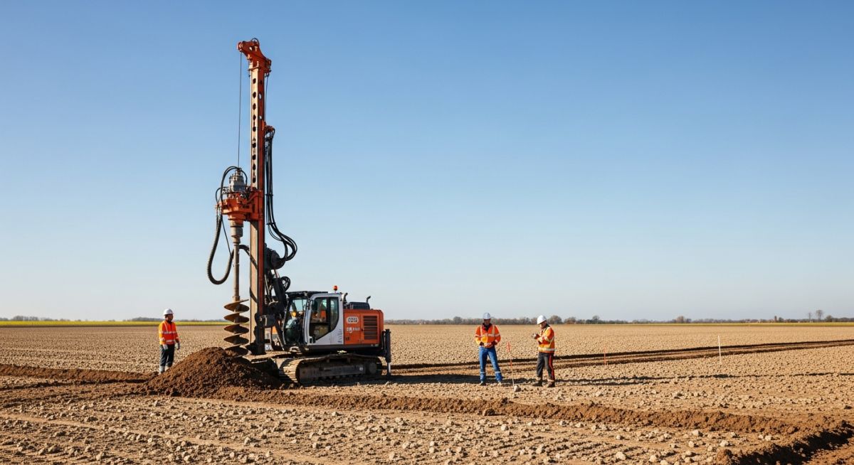
Executing a geotechnical investigation for solar farms requires a departure from standard building code approaches. Because solar arrays are sensitive to differential settlement, we focus on the lateral and axial capacity of driven piles. My experience dictates that we must perform a minimum of one borehole per 5 to 10 acres, depending on the geological complexity of the site.
Borehole Planning and Soil Mechanics
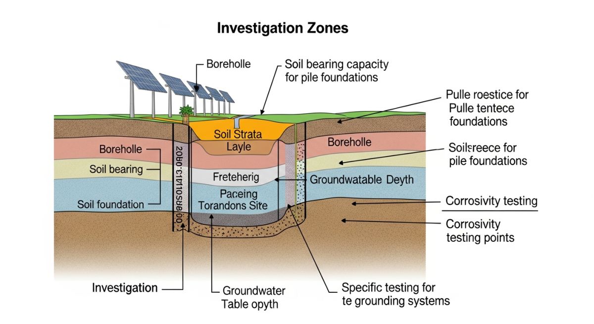
We utilize ASTM D1586 for Standard Penetration Testing (SPT) to correlate N-values with soil density. For solar projects, the critical parameter is the skin friction between the steel pile and the soil. We calculate the ultimate axial capacity (Q_u) using the alpha-method for cohesive soils or the beta-method for cohesionless soils:
Q_u = f_s * A_s + q_p * A_p
Where f_s is the unit skin friction, A_s is the surface area of the pile, q_p is the unit end bearing, and A_p is the pile tip area. In my practice, I always insist on performing at least three full-scale pile load tests (axial and lateral) to validate these theoretical calculations against site-specific conditions.
Field Warning: The Corrosivity Trap
Many developers overlook soil chemistry until the piles are already on-site. High chloride content or low pH levels can reduce the design life of galvanized steel piles by 50% or more. Always test for pH, resistivity, sulfates, and chlorides per ASTM G57 to determine if cathodic protection or increased sacrificial steel thickness is required.
Groundwater and Variability Assessment
Groundwater levels significantly influence the effective stress of the soil. During the investigation, we must record the static water level and assess the potential for seasonal fluctuations. If the water table rises, the effective unit weight of the soil decreases, which directly reduces the lateral resistance of the piles. This is a common failure point in flood-prone regions.
Finally, we must map soil variability across the site. If the site exhibits high spatial variability, we cannot rely on a single design for the entire array. We must segment the site into geotechnical zones, each with its own pile embedment depth and foundation specification, to optimize material costs without compromising structural safety.
Geotechnical Risk Mitigation: The strategic balance between upfront investigation costs and the long-term reduction of structural failure risks in utility-scale solar infrastructure.
Advantages
- Optimizes pile embedment depths, reducing steel procurement costs.
- Prevents costly mid-construction foundation redesigns.
- Provides essential data for bankability and insurance underwriting.
- Identifies potential soil-related construction hazards early.
- Ensures compliance with local building codes and safety standards.
Disadvantages
- High initial mobilization costs for drilling equipment.
- Requires significant time, potentially delaying project start dates.
- Data can be misleading if borehole density is insufficient.
- Complex soil profiles may require advanced, expensive testing.
- Does not account for future site-wide drainage modifications.
Geotechnical Engineering Deployment: The application of subsurface analysis across diverse solar project environments to ensure structural longevity and operational efficiency.
Utility-Scale Ground-Mounted Arrays
In large-scale desert or agricultural sites, geotechnical investigations are used to determine the optimal pile driving energy and depth. This ensures that the racking system can withstand high wind loads while minimizing the risk of pile pull-out in loose, sandy soils.
Brownfield Solar Redevelopment
When converting former industrial sites or landfills into solar farms, geotechnical analysis is critical for identifying contaminated soil and potential settlement issues. We must assess the structural integrity of the cap and ensure that pile installation does not compromise the environmental containment layers.
Floating Solar (FPV) Anchoring
For floating solar projects, the geotechnical investigation shifts to the lake or reservoir bed. We analyze the sediment shear strength to design the anchor systems that hold the floating platforms in place against wind and wave forces, ensuring the stability of the entire array.
High-Wind Coastal Installations
In coastal regions, geotechnical investigations focus on soil liquefaction potential and salt-induced corrosion. We perform deep-borehole testing to ensure that foundations are anchored into stable strata, preventing structural failure during extreme weather events like hurricanes or tropical storms.
When evaluating site suitability for utility-scale solar arrays, engineers must correlate soil mechanics with specific foundation types, such as driven piles, helical piers, or ground screws. The following table summarizes the critical geotechnical parameters that dictate the allowable load-bearing capacity and lateral resistance required for structural stability under wind and seismic loading conditions.
These parameters are derived from ASTM D2487 classification standards and must be verified through site-specific testing. In my experience, failing to account for the variability in these values across a large-scale site often leads to premature foundation failure or excessive material costs due to over-engineering.
| Parameter | Test Method | Significance |
|---|---|---|
| Standard Penetration Test (N-Value) | ASTM D1586 | Determines relative density and consistency for pile driveability. |
| Soil Corrosivity (pH/Resistivity) | ASTM G57 | Critical for determining steel pile service life and coating needs. |
| Undrained Shear Strength | ASTM D2166 | Essential for calculating lateral pile capacity in cohesive soils. |
Always ensure that the laboratory testing program is tailored to the specific geological formation encountered during the initial borehole drilling phase. Relying on generic regional data is a common pitfall that ignores localized soil lenses which can significantly impact foundation performance.
The following matrix maps the core technical entities encountered during a geotechnical investigation for solar farms to their respective industry standards and physical performance metrics. This mapping is designed to assist project managers and lead engineers in aligning site data with structural design requirements.
By standardizing the nomenclature and reference codes, we ensure that the geotechnical report provides actionable data for the structural team. This matrix serves as a quick-reference guide for identifying which ASTM or ISO standards govern specific soil-structure interaction phenomena.
| Entity | Standard | Primary Metric |
|---|---|---|
| Groundwater Table | ASTM D4750 | Depth to phreatic surface (meters) |
| Soil Classification | ASTM D2487 | USCS Group Symbol |
| Thermal Resistivity | ASTM D5334 | Degrees Celsius meter per Watt |
Integration of these entities into the final design package is non-negotiable for utility-scale projects. Proper documentation of these metrics ensures compliance with local building codes and provides a defensible basis for the foundation design life, typically spanning 25 to 30 years.
Geotechnical Investigation for Solar Farms requires a rigorous, systematic approach to site verification. Before finalizing the foundation design, I recommend performing a comprehensive site walk-through and data validation process to ensure that the borehole logs accurately represent the subsurface conditions across the entire project footprint.
- ☐ Borehole Spacing: Verify that borehole density meets the minimum requirements for the site size, typically one per 5-10 acres for uniform sites.
- ☐ Corrosivity Testing: Ensure soil samples are tested for pH, resistivity, and chloride content to determine the necessity of cathodic protection or sacrificial steel thickness.
- ☐ Groundwater Monitoring: Confirm that seasonal high groundwater levels have been estimated, especially in low-lying areas prone to saturation.
- ☐ Thermal Conductivity: Validate that thermal resistivity testing is performed if underground medium-voltage cabling is planned for the site.
- ☐ Slope Stability: Check for potential erosion or slope failure risks if the site topography includes significant gradients.
Each item on this checklist must be signed off by the lead geotechnical engineer. If any anomalies are discovered during the site verification, such as unexpected rock outcrops or soft organic layers, the foundation design must be adjusted immediately to prevent costly field modifications during the construction phase.
Problem: Unexpected Soil Corrosivity in Coastal Solar Project
During the construction of a 50MW solar farm, we encountered severe premature corrosion on driven steel piles within the first six months of installation.
- Initial geotechnical report failed to account for high chloride concentrations in the shallow water table.
- Soil resistivity values were measured only at the surface, missing the corrosive saline layers at pile depth.
- Steel piles were specified without adequate protective coatings for the actual site conditions.
Outcome: Remediation and Design Optimization
We successfully mitigated the issue by implementing a multi-stage corrective action plan that saved the project from total foundation failure.
- Performed deep-borehole soil chemistry analysis to map the extent of the corrosive plume.
- Installed sacrificial anodes on all existing piles to provide immediate cathodic protection.
- Updated the geotechnical investigation protocol to mandate deep-profile resistivity testing for all future coastal projects.
My recommendation for future projects is to never assume soil uniformity based on surface appearance. Always conduct deep-profile testing in coastal or high-salinity environments to ensure the long-term integrity of the structural steel.
How many boreholes are required for a standard solar farm?
- One borehole per 5 to 10 acres for sites with uniform geology.
- Increased density in areas with known subsurface variability or high-load requirements.
- Adherence to ASTM D420 guidelines for site characterization.
Why is soil resistivity testing critical for solar projects?
- Low resistivity indicates high corrosivity, requiring thicker steel or specialized coatings.
- Accurate resistivity data is essential for designing the site grounding grid to meet IEEE 80 standards.
- Testing should be performed at multiple depths to capture the full soil profile.
What is the role of thermal resistivity in solar design?
- High thermal resistivity can lead to cable overheating and insulation degradation.
- Engineers must use ASTM D5334 to determine if thermal backfill is necessary.
- Proper assessment prevents long-term electrical losses and potential system failures.
How do I handle groundwater in foundation design?
- High water tables reduce effective stress, lowering the skin friction capacity of piles.
- Seasonal fluctuations must be accounted for to prevent long-term settlement.
- Dewatering plans may be required during construction if the water table is near the surface.
What are the common pitfalls in geotechnical reporting?
- Ignoring localized soil lenses that differ from the general site classification.
- Failing to provide clear, actionable recommendations for foundation installation.
- Lack of coordination between the geotechnical team and the structural design team.
How does soil variability affect pile driveability?
- Hard layers or boulders can cause pile damage during installation.
- Soft, compressible layers can lead to excessive settlement under wind loads.
- Pre-drilling or alternative foundation types may be necessary in highly variable ground conditions.
📚 Recommended Resources: Geotechnical Investigation
Read these Guides
- 📄 Essential Geotechnical Investigations: Field and Laboratory Testing Methods Explained
- 📄 How to Read and Interpret Geotechnical Investigation Reports for Engineers
- 📄 Essential Geotechnical Investigation Terminology for Structural Foundation Design Success
- 📄 Essential Survey Instruments Used in Geotechnical Investigations for Site Analysis
Complete Course on
Piping Engineering
Check Now
Key Features
- 125+ Hours Content
- 500+ Recorded Lectures
- 20+ Years Exp.
- Lifetime Access
Coverage
- Codes & Standards
- Layouts & Design
- Material Eng.
- Stress Analysis
