Solar Pile Foundations: Essential Geotechnical Data Requirements
In my two decades of engineering experience, I have observed that the most common point of failure in utility-scale solar projects is not the PV module or the inverter, but the foundation system. Designing robust Solar Pile Foundations requires a rigorous approach to soil mechanics that many developers underestimate. When we drive piles into the earth, we are essentially betting the structural integrity of a multi-million dollar asset on the shear strength and consistency of the subsurface.
This guide outlines the specific geotechnical inputs required to move from preliminary site assessment to final structural certification. We will examine how soil strength, corrosion potential, and lateral load capacity dictate the pile embedment depth and section modulus. By aligning your site investigation with these technical requirements, you mitigate the risk of structural instability during high-wind events.
Key Takeaways
- Standardized soil testing (SPT/CPT) is mandatory for accurate pile capacity modeling.
- Corrosion data must be site-specific to determine the required sacrificial steel thickness.
- Lateral load assessment is the primary driver for pile section selection in solar arrays.
- Field load testing is the only way to validate theoretical geotechnical design assumptions.
Technical Analysis of Solar Pile Foundations
Solar Pile Foundations: These systems rely on the interaction between the pile surface and the surrounding soil matrix, governed by the principles of soil-structure interaction (SSI) and lateral earth pressure coefficients.
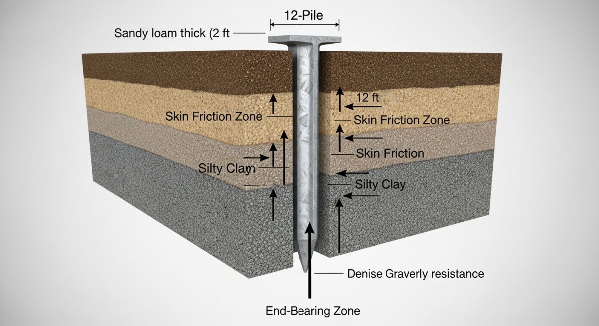
To achieve a reliable design, we must first define the soil profile. I typically require Standard Penetration Test (SPT) N-values or Cone Penetration Test (CPT) tip resistance data at intervals no greater than 1.5 meters. These values allow us to calculate the ultimate skin friction and end-bearing capacity using the alpha or beta methods for cohesive and cohesionless soils, respectively.
Lateral Load Assessment Parameters
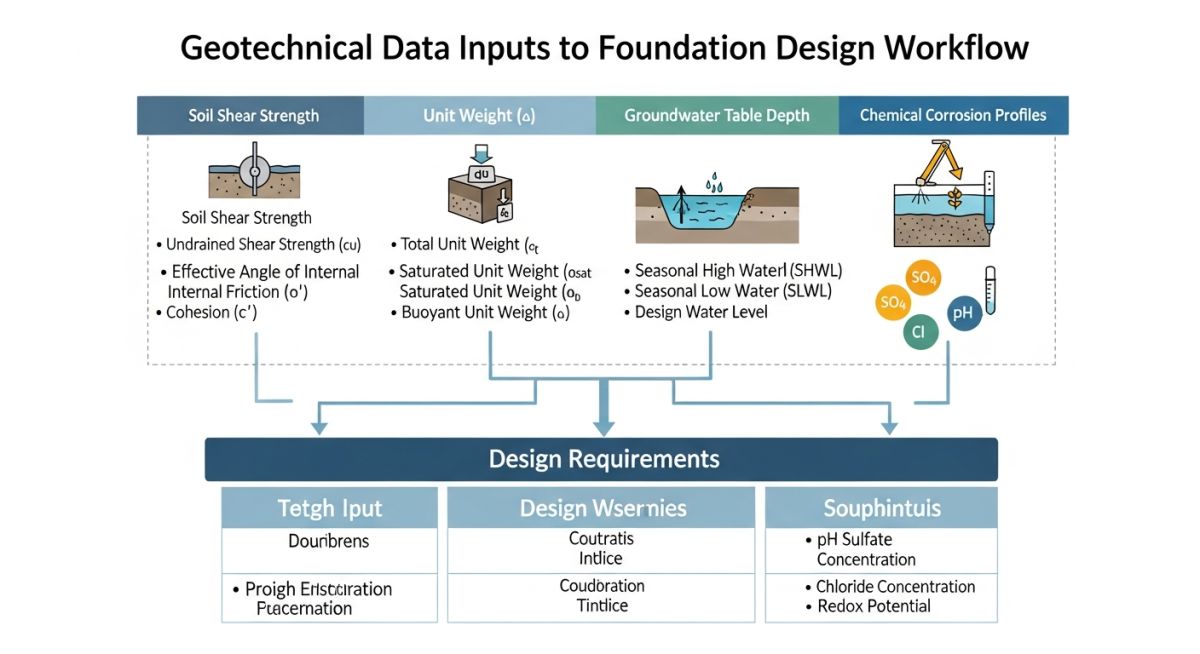
The lateral load capacity is the governing factor for most solar pile designs due to the high wind-sail area of the trackers. We utilize the p-y curve method, as defined in API RP 2GEO, to model the soil resistance as a function of pile deflection. The input parameters required for this analysis include:
- Effective Unit Weight (gamma): Essential for calculating overburden pressure.
- Angle of Internal Friction (phi): Determines the passive earth pressure resistance.
- Modulus of Subgrade Reaction (k): Defines the soil stiffness under lateral displacement.
- Undrained Shear Strength (cu): Critical for clay-heavy sites where rapid loading occurs.
Field Warning: Soil Variability
Never rely on regional soil maps for final design. I have seen projects fail because a localized lens of soft, saturated clay was missed during a sparse boring program. Always perform site-specific testing at a density that captures the variability of the subsurface strata.
Corrosion and Material Longevity
Corrosion data is often treated as an afterthought, but it is a critical input for the design life of the structure. We must analyze the soil resistivity, pH levels, and chloride/sulfate concentrations. According to NACE International standards, soil resistivity below 2000 ohm-cm indicates a highly corrosive environment, necessitating either thicker steel sections or specialized cathodic protection.
The calculation for the required steel thickness (t_req) is expressed as: t_req = t_structural + (corrosion_rate * design_life). In my experience, failing to account for the corrosion rate leads to premature structural degradation, particularly in coastal or high-salinity environments where the soil chemistry aggressively attacks the galvanized coating of the piles.
Foundation Design Trade-offs: Selecting the appropriate pile system involves balancing installation speed, cost-efficiency, and long-term structural performance against site-specific geotechnical constraints.
Advantages
- Rapid Installation: Driven piles eliminate the need for concrete curing, accelerating project timelines.
- Minimal Site Disturbance: Low-impact driving equipment preserves the existing soil structure and drainage patterns.
- Immediate Load Bearing: Piles achieve full design capacity immediately upon reaching the target embedment depth.
- Cost Predictability: Standardized steel sections allow for precise procurement and logistics planning.
Disadvantages
- Refusal Risk: Encountering unexpected bedrock or large boulders can lead to costly pile refusal and re-design.
- Corrosion Sensitivity: Steel piles are susceptible to electrochemical degradation in aggressive soil environments.
- Limited Lateral Capacity: In very soft soils, piles may require excessive embedment or bracing to meet deflection limits.
- Geotechnical Dependency: Performance is entirely reliant on the accuracy of the initial soil investigation report.
Geotechnical Foundation Deployment: These methodologies are applied across diverse terrains to ensure the stability of solar energy infrastructure under varying environmental and mechanical loading conditions.
Utility-Scale Solar Farms
In large-scale flat-terrain projects, driven piles are the industry standard for supporting single-axis trackers. The geotechnical design focuses on optimizing the pile length to resist the overturning moments generated by wind loads on the large tracker surface area.
Brownfield Redevelopment
When installing solar arrays on reclaimed land or capped landfills, pile design must account for non-homogeneous fill materials. We often utilize deeper piles to reach competent native soil, ensuring that the foundation is not compromised by the settlement of the underlying waste layers.
Coastal Renewable Installations
Projects located in high-salinity coastal zones require rigorous corrosion mitigation strategies. The geotechnical input here emphasizes soil resistivity testing to determine the necessary sacrificial steel thickness or the application of specialized epoxy coatings to prevent premature structural failure.
Designing robust solar pile foundations requires a precise translation of geotechnical site investigation data into structural load-bearing capacity models. In my experience, the primary challenge lies in correlating raw field test results, such as Standard Penetration Test (SPT) blow counts or Cone Penetration Test (CPT) tip resistance, with the specific soil-structure interaction requirements defined by ASCE 7 and ASTM D1586 standards. Engineers must account for the variability in soil stratigraphy across large-scale solar arrays, where a single site may transition from stiff clay to loose granular fill within a few hundred meters.
The following table summarizes the critical geotechnical inputs required for calculating axial and lateral pile capacities. These values serve as the foundation for determining embedment depths and section modulus requirements for C-channel or H-pile profiles. Always ensure that the soil parameters are adjusted for seasonal moisture fluctuations, as solar sites are often located in open, unpaved areas prone to significant water table shifts that directly impact skin friction and end-bearing performance.
| Parameter | Standard Reference | Design Application |
|---|---|---|
| Effective Unit Weight | ASTM D2216 | Overburden pressure and effective stress calculations |
| Internal Friction Angle | ASTM D3080 | Lateral earth pressure and skin friction coefficients |
| Undrained Shear Strength | ASTM D2166 | Short-term axial capacity in cohesive soils |
| Soil Modulus (k) | ASCE 20 | P-Y curve generation for lateral load analysis |
The integration of geotechnical data into solar structural design is a multi-disciplinary process that bridges soil mechanics and structural steel engineering. This matrix maps the physical soil properties to the corresponding structural design entities, ensuring that the pile selection—whether driven, helical, or ground-screw—is optimized for the specific site conditions encountered during the geotechnical investigation phase.
By aligning these entities, engineers can effectively mitigate risks associated with differential settlement and lateral instability, which are the most common failure modes for solar racking systems. This mapping is essential for maintaining compliance with international building codes and ensuring the long-term structural integrity of the solar array throughout its 25-to-30-year operational lifespan.
| Entity | Acronym | Standard |
|---|---|---|
| Standard Penetration Test | SPT | ASTM D1586 |
| Cone Penetration Test | CPT | ASTM D5778 |
| Soil Resistivity | SR | ASTM G57 |
| Lateral Load Test | LLT | ASTM D3966 |
Geotechnical Site Verification: Before finalizing the pile design, I always mandate a comprehensive site verification process. This ensures that the design assumptions—often based on limited borehole data—align with the actual subsurface conditions encountered during the mobilization phase. Failure to verify these parameters can lead to costly field modifications, such as pile refusal or the need for deeper embedment than initially calculated.
- Borehole Spacing: Confirm that borehole density meets the minimum requirements of ASCE 7 for the specific site area and soil complexity.
- Water Table Depth: Validate the seasonal high water table elevation to adjust skin friction calculations and corrosion potential.
- Soil Corrosivity: Verify pH, chloride, and sulfate levels against ASTM G57 to determine if protective coatings or increased steel thickness are required.
- Load Testing: Ensure at least one sacrificial pile is tested for both axial and lateral capacity prior to full-scale installation.
- Refusal Criteria: Define clear refusal criteria for driven piles to prevent structural damage to the pile head during installation.
By following this checklist, you create a robust audit trail that satisfies both the structural engineer of record and the project owner. In my experience, the most successful solar projects are those where the geotechnical report is treated as a living document, updated continuously as the installation progresses and more subsurface data becomes available.
The Problem: Unexpected Lateral Deflection
During a 50MW solar project in a region with high-plasticity clay, the installed piles exhibited excessive lateral deflection under wind loading, exceeding the design limits specified in the racking manufacturer’s manual.
- Underestimation of the soil modulus (k) in the upper 1.5 meters of the soil profile.
- Failure to account for the reduction in soil stiffness due to seasonal moisture saturation.
- Inadequate lateral load testing performed during the initial geotechnical investigation phase.
- Discrepancy between the assumed soil cohesion and the actual field-measured undrained shear strength.
The Outcome: Remediation and Design Optimization
The project team successfully stabilized the array by implementing a targeted remediation strategy that restored structural integrity and met all safety codes.
- Increased pile embedment depth by 0.8 meters to reach a more competent soil stratum.
- Installed lateral bracing for the most affected rows to redistribute wind loads.
- Updated the P-Y curve models based on new, site-specific lateral load tests.
- Implemented a real-time monitoring program to track pile movement over the first six months of operation.
Recommendation: Always perform site-specific lateral load testing in areas with high-plasticity soils. Relying solely on empirical correlations from regional geotechnical reports is a significant risk factor that can lead to project-wide structural instability.
Frequently Asked Engineering Questions
How do I determine the required pile embedment depth?
Determining embedment depth is a function of both axial and lateral load requirements. You must calculate the depth where the soil resistance matches the applied structural loads with an appropriate factor of safety, typically 2.0 to 3.0 for axial loads.
- Calculate skin friction based on soil type and effective stress.
- Determine end-bearing capacity for the pile tip.
- Perform a lateral load analysis using P-Y curves to ensure deflection limits are not exceeded.
- Verify the depth against the frost line and seasonal water table fluctuations.
What is the impact of soil corrosivity on pile design?
Soil corrosivity directly dictates the sacrificial steel thickness or the type of protective coating required for the pile. High levels of chlorides, sulfates, or low pH values accelerate the oxidation process, potentially reducing the pile’s cross-sectional area over time.
- Test soil resistivity per ASTM G57.
- Apply cathodic protection if the soil is highly aggressive.
- Increase steel wall thickness to account for the expected corrosion rate over 30 years.
- Use galvanized or epoxy-coated steel for enhanced durability in corrosive environments.
When should I use helical piles versus driven piles?
The choice between helical and driven piles depends on soil density, site accessibility, and load requirements. Helical piles are often preferred in loose, granular soils or where vibration must be minimized, while driven piles are more cost-effective for large-scale projects in stiff, consistent soil profiles.
- Helical piles provide superior uplift resistance in soft soils.
- Driven piles are faster to install in dense, rocky, or compacted soil conditions.
- Consider the installation equipment availability and site topography.
- Evaluate the total cost of ownership, including installation time and material durability.
How do I account for lateral loads in solar racking?
Lateral loads from wind and seismic events are the primary drivers of pile failure in solar arrays. You must model the soil-pile interaction using P-Y curves, which represent the soil’s resistance to lateral deflection at various depths along the pile.
- Use software like LPILE or similar geotechnical analysis tools.
- Ensure the pile section modulus is sufficient to resist bending moments.
- Account for the group effect if piles are installed in close proximity.
- Validate the model with field lateral load tests to ensure accuracy.
What are the requirements for pile load testing?
Load testing is the only way to verify that the design assumptions hold true in the field. ASTM D3966 provides the standard procedures for lateral load testing, while ASTM D1143 covers axial load testing.
- Perform tests on at least 1% of the total pile count.
- Test in representative soil conditions across the entire site.
- Document all load-deflection data for future reference and compliance audits.
- Adjust the design if the test results show significant deviations from the initial model.
How does soil moisture affect pile capacity?
Soil moisture significantly alters the shear strength and stiffness of the soil, which directly impacts both axial and lateral pile capacity. In cohesive soils, increased moisture leads to a reduction in undrained shear strength, while in granular soils, it can lead to pore pressure buildup.
- Account for the worst-case seasonal moisture content in your design.
- Use effective stress parameters for long-term capacity calculations.
- Consider the impact of drainage conditions on the rate of load application.
- Monitor the site for signs of soil saturation or poor drainage during the construction phase.
Complete Course on
Piping Engineering
Check Now
Key Features
- 125+ Hours Content
- 500+ Recorded Lectures
- 20+ Years Exp.
- Lifetime Access
Coverage
- Codes & Standards
- Layouts & Design
- Material Eng.
- Stress Analysis
