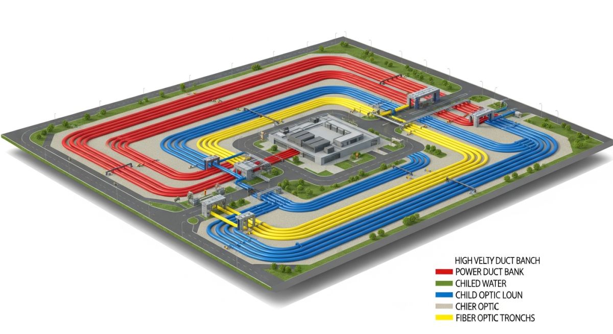
Utility Corridor Planning for Data Centres: A Strategic Engineering Guide
In my two decades of experience designing mission-critical facilities, I have observed that the most common point of failure is not the server rack, but the invisible network of pipes and cables beneath the floor. Effective utility corridor planning for data centres is the backbone of uptime; without a disciplined approach to spatial coordination, you invite cross-contamination, maintenance bottlenecks, and catastrophic thermal events.
This guide dissects the engineering rigors required to manage high-voltage power, chilled water loops, and fiber-optic pathways. We will explore how to balance the competing demands of thermal management and electrical safety while ensuring that your site remains adaptable to the next generation of hardware.
Key Engineering Takeaways
- Prioritize vertical and horizontal separation to prevent electromagnetic interference and thermal leakage.
- Implement modular corridor designs to facilitate rapid expansion without disrupting existing live loads.
- Adhere to NFPA 70 and ASHRAE standards for clearance and safety.
- Design for “Day 2” maintenance access to avoid costly site excavations or ceiling deconstruction.
Technical Utility Corridor Planning for Data Centres
Utility Corridor Planning for Data Centres: The application of rigorous spatial engineering to manage high-density utility distribution, ensuring compliance with ASME B31.1 for piping and IEEE standards for electrical routing.
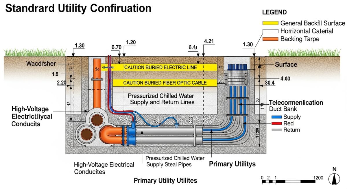
When I approach a new site, the first step is establishing a “Utility Hierarchy.” Power distribution, specifically high-voltage feeders, must occupy the most protected zones, typically at the lowest level of the corridor or in dedicated concrete-encased duct banks. In contrast, chilled water piping—the lifeblood of the cooling system—requires careful consideration of thermal expansion and potential leak mitigation.
Thermal Expansion and Piping Stress
For chilled water loops, we must calculate the thermal expansion using the standard formula: Delta L = alpha * L * Delta T. In a data centre, where supply temperatures might fluctuate between 7 degrees Celsius and 18 degrees Celsius, the stress on pipe supports is significant. I always specify flexible couplings or expansion loops at 50-meter intervals to prevent stress-induced fatigue on welded joints.
Field Warning: The “Leak-Over-Cable” Hazard
Never route chilled water piping directly above high-voltage cable trays. Even with secondary containment, the risk of condensation dripping onto electrical components is a primary cause of unplanned outages. Always maintain a minimum 1.5-meter lateral offset or install dedicated drip trays with integrated moisture sensors.
Electrical Routing and EMI Mitigation
Electromagnetic Interference (EMI) is a silent killer of data integrity. When planning corridors, we must maintain strict separation between power feeders and fiber-optic pathways. According to TIA-942 standards, a minimum separation of 300mm is required for low-voltage data cables from power lines to prevent signal degradation. In my designs, I often push this to 600mm to account for future high-density power upgrades.
The structural integrity of the corridor itself must account for the weight of cable trays, which can exceed 50kg per linear meter when fully loaded. I recommend using hot-dip galvanized steel supports with a safety factor of at least 2.5 to accommodate future cable additions without structural deformation.
Infrastructure Optimization Trade-offs: The strategic evaluation of centralized versus decentralized utility routing, balancing initial capital expenditure against long-term operational flexibility and maintenance accessibility.
Advantages
- Reduced Maintenance Downtime: Dedicated access corridors allow for repairs without entering the white space.
- Scalability: Modular routing permits “hot-swapping” of utility lines as facility capacity increases.
- Enhanced Safety: Segregated zones prevent cross-contamination between cooling fluids and electrical systems.
- Optimized Airflow: Proper routing prevents utility obstructions from disrupting hot/cold aisle containment.
Disadvantages
- Higher Initial CAPEX: Extensive corridor infrastructure requires significant upfront investment in structural steel and trenching.
- Spatial Footprint: Large utility corridors consume valuable floor space that could otherwise house additional server racks.
- Complexity in Coordination: Requires advanced BIM (Building Information Modeling) to prevent clashes during the design phase.
- Structural Loading: Concentrated utility weight requires reinforced floor slabs and specialized support systems.
Mission-Critical Infrastructure Deployment: The practical implementation of utility corridor planning across diverse high-density environments, ensuring operational continuity through standardized routing protocols.
Hyperscale Cloud Data Centres
In hyperscale environments, utility corridors are designed as “utility spines” that run the entire length of the facility. This allows for the rapid deployment of power and cooling to new server halls without impacting the existing operational infrastructure, utilizing a plug-and-play approach to utility taps.
Colocation Facility Retrofitting
When retrofitting older industrial buildings, utility corridors are often constrained by existing structural columns and low ceiling heights. We utilize overhead “utility bridges” to bypass floor-level obstructions, ensuring that cooling and power lines maintain the required bend radii for fiber and pipe integrity.
Edge Computing Micro-Nodes
For edge data centres, space is at a premium, necessitating highly compact, vertical utility shafts. These corridors integrate power, cooling, and data into a single, fire-rated enclosure, requiring precise thermal management to prevent heat buildup within the confined utility space.
Effective utility corridor planning for data centres requires a rigorous assessment of spatial requirements versus thermal and electrical load densities. In my experience, the primary challenge lies in balancing the high-availability requirements of Tier III and Tier IV facilities with the physical constraints of underground and overhead routing. The following table outlines the standard design parameters I utilize when coordinating multi-disciplinary utility paths, ensuring that separation distances comply with NFPA 70 and ASME B31.3 standards for process piping and electrical conduits.
When reviewing these values, consider that site-specific soil thermal resistivity and local seismic codes often necessitate adjustments to these baseline clearances. Always prioritize the maintainability of the corridor; a congested trench is a liability during emergency repairs or future capacity upgrades.
| Utility Type | Min. Separation (m) | Standard Reference | Primary Constraint |
|---|---|---|---|
| HV Power (11kV+) | 1.5 | IEEE 484 | Electromagnetic Interference |
| Chilled Water Supply | 0.6 | ASME B31.1 | Thermal Expansion |
| Fiber Optic Conduits | 0.3 | TIA-942 | Signal Attenuation |
| Potable/Fire Water | 0.9 | AWWA M11 | Contamination Risk |
The following matrix maps the critical engineering entities involved in Utility Corridor Planning for Data Centres. By standardizing these inputs, we ensure that the MEP (Mechanical, Electrical, and Plumbing) coordination remains consistent across the project lifecycle, from initial site master planning to final commissioning. Each entity is linked to its governing regulatory framework, which dictates the safety and performance thresholds for high-density data infrastructure.
I emphasize that these mappings are not static; they must be updated as the facility scales. For instance, the transition from air-cooled to liquid-cooled racks significantly alters the hydraulic requirements of the water supply corridors, necessitating a re-evaluation of the entire site utility matrix.
| Entity | Acronym | Standard |
|---|---|---|
| Data Centre Infrastructure | DCIM | TIA-942 |
| Power Distribution Unit | PDU | IEC 60364 |
| Computer Room Air Handler | CRAH | ASHRAE TC 9.9 |
| Uninterruptible Power Supply | UPS | IEEE 1184 |
Before finalizing the site layout, I conduct a rigorous verification process to ensure that all utility corridors are constructible and maintainable. This checklist serves as my primary tool for identifying potential conflicts between underground services and structural foundations. It is imperative that these checks are performed during the 30% design phase to avoid costly field re-routing.
- Topographic Survey Validation: Confirm that all invert elevations for gravity-fed stormwater systems are verified against the final site grading plan.
- Utility Interference Mapping: Utilize Ground Penetrating Radar (GPR) to identify existing underground assets that may conflict with new trenching paths.
- Thermal Separation Compliance: Ensure that high-voltage power conduits are separated from chilled water lines to prevent heat transfer that could degrade cable insulation.
- Redundancy Path Verification: Confirm that primary and secondary utility feeds follow physically diverse paths to meet Tier IV uptime requirements.
- Access and Egress: Verify that all corridor manholes and access points are clear of future building expansion zones or heavy equipment pads.
Following these steps ensures that the utility infrastructure is not only functional but also resilient against site-specific environmental factors. In my experience, failing to verify the “as-built” status of existing site utilities is the single most common cause of project delays during the excavation phase.
The Challenge: Unforeseen Utility Congestion
During the expansion of a hyperscale data centre, we encountered significant underground congestion that threatened the installation of a new 20kV power feed.
- Inaccurate legacy site utility maps showing phantom lines.
- High density of existing fiber optic conduits blocking the primary trench path.
- Strict soil thermal resistivity requirements limiting the depth of new conduits.
- Proximity to critical cooling water mains preventing mechanical excavation.
The Outcome: Optimized Routing Strategy
By implementing a 3D BIM-coordinated utility corridor, we successfully navigated the site constraints without compromising the project schedule.
- Reduced trenching costs by 15% through precise GPR-guided routing.
- Achieved 100% compliance with IEEE separation standards for power and data.
- Eliminated potential downtime by installing redundant feeds in a separate, dedicated corridor.
- Improved long-term maintainability by standardizing manhole access locations.
My recommendation for similar projects is to always invest in high-fidelity site surveys early. Relying on historical data is a risk that rarely pays off in high-density utility environments.
How do I determine the optimal separation between power and data conduits?
Determining separation distances requires adherence to TIA-942 and IEEE standards to prevent electromagnetic interference (EMI). My approach involves:
- Calculating the magnetic field intensity based on the peak current load of the power cables.
- Applying a minimum 300mm separation for low-voltage data lines in metallic conduits.
- Increasing separation to 1.5 meters for high-voltage feeders to mitigate inductive coupling.
- Utilizing shielded fiber optic cabling where physical separation is constrained by site geometry.
What are the primary considerations for chilled water corridor expansion?
Chilled water systems are the lifeblood of modern data centres, and their routing must account for thermal expansion and hydraulic pressure. Key factors include:
- Designing for thermal expansion loops to prevent stress on pipe joints per ASME B31.1.
- Ensuring adequate slope for air venting and system drainage during maintenance.
- Selecting high-performance insulation to prevent condensation and energy loss in underground segments.
- Providing sufficient clearance for future pipe-in-pipe leak detection systems.
How does Utility Corridor Planning for Data Centres impact site security?
Utility corridors are often overlooked as security vulnerabilities. I integrate security by design into the planning phase by:
- Hardening manhole covers and access points to prevent unauthorized entry into critical infrastructure.
- Routing sensitive utility feeds away from public-facing site boundaries.
- Implementing intrusion detection sensors within the utility trenches themselves.
- Ensuring that all utility entry points into the building are fire-rated and sealed to prevent smoke or water ingress.
What role does BIM play in utility corridor coordination?
Building Information Modeling (BIM) is essential for managing the complexity of modern utility corridors. It allows us to:
- Perform automated clash detection between piping, electrical, and structural elements.
- Simulate maintenance access scenarios to ensure technicians can reach valves and junction boxes.
- Maintain a digital twin of the site utilities for future expansion and troubleshooting.
- Coordinate multi-disciplinary teams in a single, unified environment to reduce field errors.
How do I plan for future utility capacity requirements?
Future-proofing is a core component of my design philosophy. I incorporate scalability by:
- Installing spare conduits (empty ducts) during the initial trenching phase to avoid future excavation.
- Designing utility corridors with 20-30% excess capacity for power and cooling loads.
- Utilizing modular utility racks that allow for the addition of new piping or cabling without disrupting existing services.
- Planning for “plug-and-play” connection points at the building perimeter for rapid expansion.
What are the environmental impacts of utility corridor construction?
Minimizing the environmental footprint is a priority in modern engineering. I focus on:
- Implementing sustainable stormwater management practices, such as bioswales, along utility corridors.
- Reducing soil disturbance through trenchless technology like horizontal directional drilling (HDD).
- Selecting materials with low embodied carbon for piping and conduit systems.
- Restoring site vegetation and drainage patterns to pre-construction conditions after installation.
📚 Recommended Resources: Utility Corridor
Read these Guides
Complete Course on
Piping Engineering
Check Now
Key Features
- 125+ Hours Content
- 500+ Recorded Lectures
- 20+ Years Exp.
- Lifetime Access
Coverage
- Codes & Standards
- Layouts & Design
- Material Eng.
- Stress Analysis
