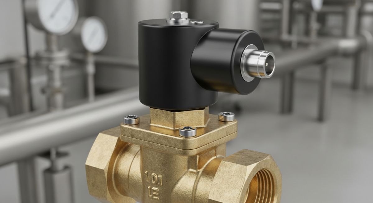
What is a Solenoid Valve and What is its Types?
In my 20 years of piping engineering, I have seen countless instrument air lines, chemical dosing skids, and safety shutdown systems fail for one simple reason: an incorrectly specified solenoid valve. These compact, electromechanical workhorses are the critical link between digital control systems and physical fluid flow. When a DCS commands a valve to trip, or when a batch controller demands precise chemical injection, it is the solenoid valve that executes the physical transition.
Choosing the wrong type of valve—such as installing a pilot-operated unit where a direct-acting design is required—can lead to system-wide operational headaches, including line chatter, coil burnouts, or complete failure to actuate. In this comprehensive guide, I will share my field-tested insights into how these valves operate, their distinct classifications, and how to select the correct design for your specific piping network.
Key Engineering Takeaways
- Understand the fundamental mechanical differences between direct-acting, pilot-operated, and semi-direct acting designs.
- Learn how to calculate the required flow coefficient (Cv) and avoid common sizing pitfalls.
- Identify the critical role of minimum operating pressure differential (MOPD) in valve actuation.
- Discover field-proven installation practices to maximize coil life and prevent premature elastomer failure.
How Does a Solenoid Valve Control Flow?
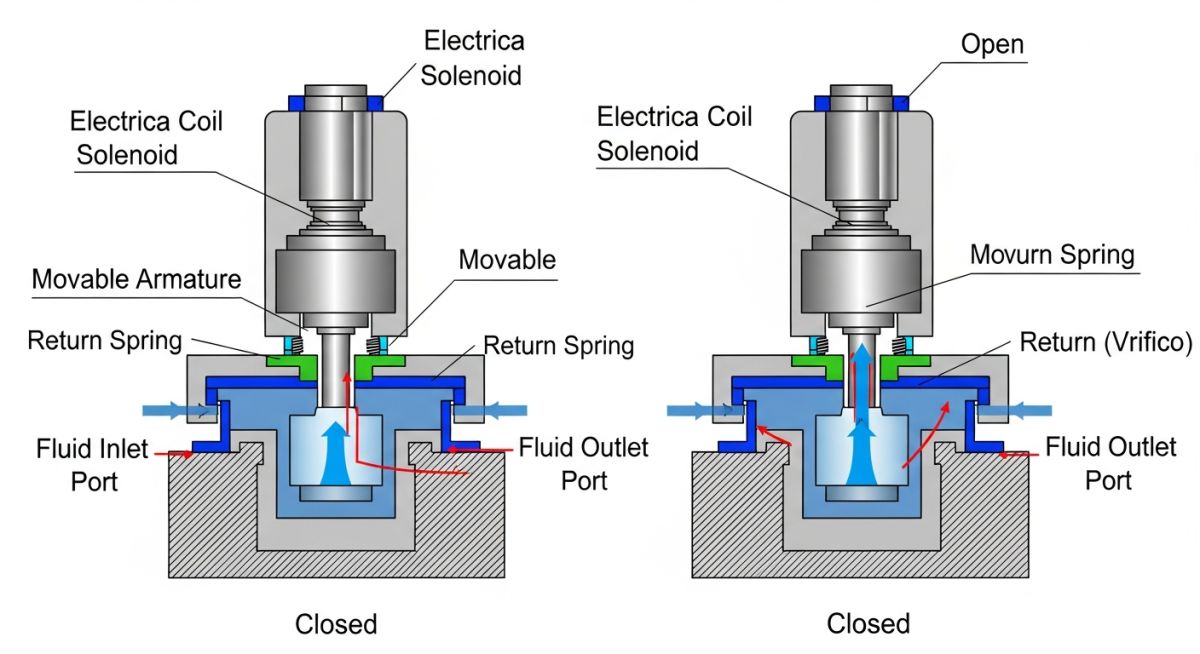
Solenoid Valve Operation: The process of utilizing electromagnetic force generated by an energized copper coil to overcome mechanical spring tension, thereby lifting or depressing a sealing plunger to regulate fluid passage through a calibrated flow path.
To truly understand a solenoid valve, we must break down its physics. The assembly consists of two primary components: the solenoid operator (the electrical coil and armature) and the valve body (the pressure-containing housing and orifice). When an electrical current passes through the copper windings of the coil, it generates a magnetic field. This field concentrates along the metallic sleeve, pulling the ferromagnetic plunger upward toward the core.
In a standard normally closed (NC) valve, this movement compresses an internal return spring, lifting the elastomer seal off the valve seat and opening the flow path. When the electrical current is cut, the magnetic field collapses, and the return spring forces the plunger back down to seal the orifice. A normally open (NO) valve operates in reverse, using the magnetic force to push the plunger down and close the flow path.
In my field inspections, the most common error I encounter is the installation of a pilot-operated solenoid valve in a gravity-fed or low-pressure loop. Pilot-operated valves do not rely solely on electromagnetic force to open; they require a minimum pressure differential (typically 0.3 to 1.5 bar) between the inlet and outlet ports to lift the main diaphragm. If your system pressure drops below this threshold, the valve will remain closed or only partially open, causing severe flow restriction and potential coil burnout.
Sizing and Flow Calculations
Sizing a solenoid valve solely based on the nominal pipe size is a recipe for system failure. Instead, we must calculate the flow coefficient (Cv), which represents the volume of water in gallons per minute at 60 degrees Fahrenheit that will flow through the valve with a pressure drop of 1 psi.
For liquid service, the standard sizing equation is:
Where:
Q = Flow rate in gallons per minute (GPM)
SG = Specific gravity of the fluid (Water = 1.0)
dP = Pressure drop across the valve in psi (P1 – P2)
If you undersize the valve (resulting in a Cv that is too low), the pressure drop across the valve will be excessively high, leading to flashing, cavitation, and accelerated wear of the internal elastomer seals. Conversely, oversizing the valve can cause rapid cycling, unstable flow control, and premature mechanical failure of the plunger assembly.
For gas applications, the calculation must account for compressibility and temperature. In these scenarios, I always refer to the guidelines established in ISA-75.01.01 to ensure accurate sizing and prevent choked flow conditions.
Selecting the Right Solenoid Valve Type
Solenoid Valve Selection: The systematic evaluation of process fluid properties, operating pressures, temperature limits, and electrical classifications to match a specific valve design with industrial piping requirements.
To assist project engineers in making the correct design choices, I have compiled a comprehensive comparison table detailing the operational limits, advantages, and typical applications of the three primary solenoid valve configurations.
| Valve Design Type | Operating Mechanism | Min. Pressure Required | Flow Capacity (Cv) | Primary Applications |
|---|---|---|---|---|
| Direct-Acting | Coil force directly lifts the plunger to open the main orifice. | 0 bar (Zero differential) | Low to Moderate (Typically < 1.5) | Analytical instruments, low-pressure dosing, vacuum systems. |
| Pilot-Operated | Coil opens a small pilot port; line pressure lifts the main diaphragm. | 0.3 to 1.5 bar (Required) | High to Very High (Up to 50+) | High-flow water distribution, high-pressure air lines, fire protection. |
| Semi-Direct Acting | Coil is mechanically linked to the diaphragm, assisting in lift. | 0 bar (Zero differential) | Moderate to High | Fuel gas trains, low-pressure water systems, batching loops. |
When writing procurement specifications for projects governed by ASME B31.3, you must specify the exact material and electrical classifications. The matrix below maps these critical engineering parameters.
| Component / Parameter | Specification Standard | Material / Type Options | Engineering Application Note |
|---|---|---|---|
| Elastomer Seals | ASTM D1418 / FDA | NBR, FKM (Viton), EPDM, PTFE | Use EPDM for hot water/steam; use FKM for hydrocarbons and acids. |
| Coil Insulation Class | NEMA ST 20 / IEC 60085 | Class F (155°C), Class H (180°C) | Class H is highly recommended for continuous duty in high ambient areas. |
| Enclosure Rating | NEMA 250 / IEC 60529 | NEMA 4 (IP65), NEMA 7 (Explosion Proof) | NEMA 7 is mandatory for Class I, Div 1 hazardous process environments. |
| Body Material | ASTM A351 / ASTM B16 | Brass, 316 Stainless Steel, PVDF | Stainless steel is required for corrosive chemical dosing and offshore use. |
How to Verify Solenoid Valve Installations
Solenoid Valve Verification: A field-level quality assurance protocol executed prior to system commissioning to verify mechanical alignment, electrical wiring integrity, and pressure boundary tightness in accordance with API 598.
Before energizing any control loop, the construction and commissioning teams must perform a rigorous physical inspection. Over my career, I have compiled this field checklist to prevent common installation errors that lead to immediate valve failure or unsafe operating conditions.
Pre-Commissioning Field Checklist
-
Flow Direction Verification: Confirm that the arrow cast or stamped on the valve body points in the direction of actual process flow. Reverse installation will cause the valve to bypass or fail to shut off.
-
Coil Orientation: Ensure the solenoid coil is mounted vertically upright (within 15 degrees of vertical). Mounting a coil upside down allows particulate matter to settle in the plunger tube, leading to sticking.
-
Electrical Conduit Seal: For hazardous areas, verify that the explosion-proof conduit seal (Y-fitting) is poured with approved compound to prevent gas migration into the electrical system.
-
Upstream Strainer Installation: Verify that a 50-mesh or finer strainer is installed upstream of the valve. Solenoid valves have extremely tight clearances; even tiny particles can plug the pilot orifice.
-
Voltage and Frequency Match: Double-check that the supply voltage (e.g., 24VDC, 120VAC) matches the rating printed on the coil nameplate. Applying incorrect voltage will permanently damage the coil.
Field Case Study: Real-World Application
The Problem: Intermittent Failure in a Gravity-Fed Diesel Loop
During the commissioning of an emergency generator fuel supply system at a critical data center, the diesel transfer line failed to deliver fuel when commanded. The system utilized a 2-inch pilot-operated solenoid valve installed on a gravity-fed line from an overhead day tank. The static head pressure was only 0.15 bar.
Because the pilot-operated valve required a minimum pressure differential of 0.5 bar to lift the main diaphragm, the valve remained closed despite the solenoid coil being fully energized. The coil began to overheat rapidly as it tried to hold the plunger open against the unbalanced hydraulic forces, risking a premature electrical burnout.
The Outcome: Retrofitting with a Semi-Direct Acting Valve
I was called to the site to troubleshoot the system. After reviewing the piping isometric drawings and calculating the static head, I recommended replacing the pilot-operated valve with a 2-inch semi-direct acting (zero-differential) solenoid valve with FKM seals.
Because the semi-direct acting valve mechanically links the solenoid plunger directly to the diaphragm, it successfully opened the flow path at zero differential pressure. The system was re-tested, and fuel flow was established within 500 milliseconds of coil energization, meeting the strict emergency response criteria of the facility.
My Professional Recommendation: Always perform a hydraulic static head calculation for gravity-fed systems. If your minimum operating pressure differential is less than 0.3 bar, do not specify a pilot-operated valve. Instead, select a direct-acting or semi-direct acting design to ensure reliable operation.
Frequently Asked Engineering Questions
What causes a solenoid valve coil to burn out?
Can a solenoid valve operate in both flow directions?
What is the difference between normally open and normally closed valves?
Why does my pilot-operated solenoid valve hum or chatter?
How does fluid viscosity affect solenoid valve performance?
What is the purpose of a shading ring in an AC solenoid valve?
===FAQ_BLOCK===
Complete Course on
Piping Engineering
Check Now
Key Features
- 125+ Hours Content
- 500+ Recorded Lectures
- 20+ Years Exp.
- Lifetime Access
Coverage
- Codes & Standards
- Layouts & Design
- Material Eng.
- Stress Analysis

📚 Recommended Resources: Solenoid Valve
Read these Guides


Related posts:
![Cross-section diagram showing a steel solar pile foundation embedded in layered soil profiles for structural analysis.]()
Essential Geotechnical Pile Design Data for Utility-Scale Solar Structures
![Professional surveyor conducting Topographical Surveys for Solar Projects on a large-scale utility site with complex terrain.]()
Topographical Surveys for Solar Projects: A Technical Engineering Guide
![A geotechnical drill rig performing soil sampling on a large, open field intended for a utility-scale solar farm project.]()
Geotechnical Investigation for Solar Farms: Essential Site Design Guide
![Isometric site plan showing Utility Corridor Planning for Data Centres with color-coded power, water, and telecom infrastructure paths.]()
Utility Corridor Planning for Data Centres: A Strategic Engineering Guide
![Aerial view of a data centre site showcasing perimeter drainage systems, detention basins, and site grading for flood prevention.]()
Drainage Design Considerations for Data Centres: A Technical Guide
![Professional surveyor using a Total Station on a large data centre construction site for topographical mapping.]()
Topographical Surveys for Data Centre Projects: A Technical Guide